This thread has been locked.

If you have a related question, please click the "Ask a related question" button in the top right corner. The newly created question will be automatically linked to this question.

UART receives wrong upper nibble

Other Parts Discussed in Thread: MSP430F5529, MSP430F5308

We have developed a design using an MSP430F5529. I now have multiple prototype boards with the same circuit. I have tested 4 boards, and so far 2 of them have a bad UART. I am told that we have 3 other units in which the UART doesn't work, but I haven't had access to see if it is the same problem.

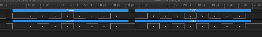
We are using the UART to communicate to a PC. I am using an MSP430 development kit with some jumpers removed as a serial to UART converter. On the two boards I have been able to examine, the upper nibble in the received byte is getting mangled. On one board 0xAA always gets received as 0xCA (as seen in the debugger), for instance.

I checked the RX line with a scope to make sure I was transmitting the correct data, and I am. I tried changing the baud rate from 115200 to 9600, but it still mangles the upper nibble in the same way. The lower nibble always transmits OK, so I don't think it is a baud rate problem. I put the same code on the two boards that work, so I don't think it is a coding error.  Since it is only the upper nibble that is bad, but the lower nibble comes through OK, I don't think it's a hardware design issue per se.

All that leads me to believe the UARTs were damaged some how, but I don't understand how only the upper nibble on both UARTs was damaged, without toasting the entire thing. Also, we are not using any current limiting resistors, or anything else, so it is possible that it was damaged via ESD, or something, but again, I feel like that would likely have taken out the whole RX line, but just the upper nibble.

Can any one offer any suggestions?

  • Are you sending just one byte at a time or have you been sending a stream of bytes? When you send a stream of bytes, is only the first byte corrupted or do all the bytes have the upper-nibble-corruption? (Make sure the stream does not have extra time-spaces between the bytes by looking at them on a scope. Often times, a lot of Windows programs do not send a stream of bytes out the serial as you would expect).
  • The software (LabVIEW) I'm using sends one byte at a time in a loop, so there are spaces between the bytes. Trying to send or receive multiple bytes at a time sometimes causes problems with the Visa drivers and serial to USB devices. Each byte looks OK though when I view it on a scope, and there are spaces between each byte. Every byte has the upper nibble issue.

    Why do you think sending one byte at a time would cause problems? And if it does cause problems, why would it only cause problems on certain units?
  • I am not saying single byte is the problem. But sending a stream of bytes with no time space in between may give clues on what is happening.

    One thing that can happen is if there is a slight shift in timing (baud). I was suspicious because the corruption was near the MSb, which are the last bits of each byte. If timing was slightly off, that may explain that. This can be caused by an inaccurate crystal, bad settings for the system clock, or something else that can cause clock timing to be off.

    What about making the board talk to itself? Connect tx to rx on the same board. Send some bytes and see what it receives.

  • UART transmits least significant bit first, most significant bit last.

    Any discrepancy in baudrate between the two parties causes timing error and that timing error accumulates. For example a 4% error in bauddrate will cause only 4% timing error for the first bit but will cause 8*4%=32% timing error in the 8th bit. The end result is, the lower nibble may be received correctly, but the upper nibble may not.

    Check the accuracy of the baudrate of your UARTs.
  • Jo-Jo Smith said:
    Can any one offer any suggestions?

    First suggestion would be: post your source code. It is highly unlikely that your UARTs are bad (at least not with this problem description). More likely, the problem is in your code.
    Some thoughts: you may use LPM3. This may switch off the clock for the UART. When a start bit is detected, the clock is re-enabled, but this takes some time. If it is more than 1/2 bit, this may cause the incoming byte to be mangled. See about wakeup times in the datasheet. Since these values differ between different MSPs (after all, physical signals are analog, even if one prefers to think of them as digital), some may work, other won’t, with the same code.

  • "... On one board 0xAA always gets received as 0xCA (as seen in the debugger), ...)"

    For that board, if you decrease the UCBRx setting by ~6%, you will see the correct byte being received.
  • I just realized I said we were using an MSP430F5529. I was using a development kit with that part, but we are actually using a MSP430F5308 on the prototype. I don't think it matters for this problem, but I wanted to correct the post just in case.

    It looks like the bad boards do indeed have a slower baud rate than the good ones. I made some captures with a logic analyzer I received yesterday, and it is obvious.  I can't figure out how to attach files to these posts, so I can't include the images unless someone tells me how.  

    I made sure that I had the exact same firmware on the good and bad board.  Here is my UART initialization code:

       P4SEL |= BIT4+BIT5;                     //P4.4,5 = USCI_A1 TXD/RXD

       UCA1CTL1 |= UCSWRST;                    //Put state machine in reset

       UCA1CTL1 |= UCSSEL_2;                   //Use SMCLK

       UCA1BR0 = 173;                          //20MHz / 173 = 115,607 or ~115200 (see User's Guide)

       UCA1BR1 = 0;

       UCA1MCTL |= UCBRS_1 + UCBRF_0;          //Modulation UCBRSx=1, UCBRFx=0

       UCA1CTL1 &= ~UCSWRST;                   //Initialize USCI state machine

       UCA1IE |= (UCRXIE | UCTXIE);            //Enable TX and RX interrupt

    I'm not sure if it matters, but we are not using an external high speed crystal. I am using the PLL instead.  However, I checked the system timing on the bad board by toggling a GPIO in a 1ms interrupt, and checking it with a scope. It was 1 ms pretty much exactly.

    Why might the two UART baud rates be different?

  • "... However, I checked the system timing on the bad board by toggling a GPIO in a 1ms interrupt, and checking it with a scope. It was 1 ms pretty much exactly. ..."

    If you change the Timer to overflow at 173-1 count, what is the frequency of that GPIO pin? Note that 173 is the UART baud-rate divider you used.
  • Jo-Jo Smith said:
     I can't figure out how to attach files to these posts

    There's a 'use rich text formatting' link. It calls the rich text editor. It allows attaching files and even drag&drop pictures.

    Jo-Jo Smith said:
    I am using the PLL instead

    It's an FLL. While a PLL compare the phase of a reference clock with the phase of the generated multiple, to tune its oscillator on analog side (which eats lots of power), the FLL digitally compares two frequencies and changes the DCO settings. This consumes almost no power, but adjustment is slow and the resulting output has some jitter.

    If you do not use a reference crystal, the resulting average frequency depends on the precision of the internal REFO, which still has some error and drift. Usually, it is still precise enough for a serial connection, but this isn't guaranteed.

  • I don't really catch your drift.  I did notice that the RTCTIM0 value seems to be a smaller number than I would expect, but it works the same on both the good and bad boards, and anyway it isn't off by as much as I would expect would be needed to cause the UART issue I am seeing.  Here is my timer initialization code:

        WDTCTL = WDTPW | WDTHOLD;                   //Stop watchdog timer

        __bis_SR_register(SCG0);                    //Disable the FLL control loop

        UCSCTL0 = 0x0000;                           //Set lowest possible DCOx, MODx

        UCSCTL1 = DCORSEL_4;
        UCSCTL2 = FLLD_0 | 610;                     //(610 + 1) * 32768 = ~20 MHz

        __bic_SR_register(SCG0);                    //Enable the FLL control loop

        __delay_cycles(625000);                     //Wait for DCO to settle: cycles = 32 x 32 x 20 MHz / 32,768 Hz

        RTCCTL01 = RTCTEVIE + RTCSSEL_1 + RTCTEV_1; //RTC interrupt enabled, source = SMCLK (20 MHz), 16-bit overflow event
        RTCTIM0 = 0xB4C4;                           //Interrupt once every ms

    I don't see how this can be just a configuration issue, since it is working on most of the board so far. At the moment I have five of them. Three of them work, and two of them don't work.

    Here are the two screen caps. The bad one is first obviously. I had the same firmware on both boards. It look like the peripheral clock on the first one is just running slow.

  • Sorry, I meant FLL, not PLL.

    I was slightly worried about it not being entirely accurate, and maybe jittery, when I ran it at 20 MHz, but is it really possible that it could cause the kind of error seen in the above screen caps?

    And would there be that much variation between micros?
  • DCO variation is quite large across different micros even of the same type.
    The DCO also ha sonly 256 different frequencies (Which drift). Modulation produces 31 more average frequencies between these 256, and with a divider as large as you have, the average is fine.
    However, your problem is the RSEL range you picked. For RSEL_4, the DCO can be between 1.3MHz and 23.2MHz, but only 3.2to12.3MHz are guaranteed for all devices. Use RSEL_5, which has a maximum frequency of 6MHz for DCOx=0 and a minimum frequency of 23.7MHz for DCOx=31. So all devices will be able to produce something around 20MHz with RSEL_5. RSEL_6 would do too, and even RSEL_7 (but in this case, chances are that the FLL will settle with DCOx=0, which would set DCOFFG)
  • Changing to RSEL_5 seems to have fixed this board. I assume it fixed the rest also.

    Thanks for the help.
  • Jo-Jo Smith said:
    I don't really catch your drift.

    LOL. Was the pun intentional or accidental?

    Jo-Jo Smith said:
    MSP430F5308

    I am going to assume you are using REFO to source the FLL? According to the datasheet, the frequency tolerance is +/- 3.5% over voltage/temperature/process variations (PVT).

  • Yes, REFO isn't the most precise reference. However, it usually (for 'normal' operating parameters 3V, 25-30°C) is good enough for RS232 operation.
    The DCO being on some devices unable to reach 20MHz on RSEL_4 is a sure cause for failure. Even more epic failure than observed.
  • Can you tell me where the 3.5% number came from? I can't seem to find a reference to it in the datasheet.
  • Table on Page 60 of the current datasheet. "Internal Reference, Low-Frequency Oscillator (REFO)"
    --> "REFO absolute tolerance calibrated"

**Attention** This is a public forum