


Dear TI Community,
I have some questions about MSP430F5529 Clock setting and accuracy. My goal is to generate 16MHz MCLK and 8MHz SPI clock in order to communicate with ADS1258. But at first I would like to be familiar with the F5529 clock settings and calibration.
At first I have setup the LP to use XT2 source
void UseXT2Clock(void)
{
	GPIO_setAsPeripheralModuleFunctionInputPin(GPIO_PORT_P5,GPIO_PIN2);
	GPIO_setAsPeripheralModuleFunctionOutputPin(GPIO_PORT_P5,GPIO_PIN13);

	UCS_setExternalClockSource(32000,4000000);
	UCS_XT2Start(UCS_XT2DRIVE_4MHZ_8MHZ);

	UCS_clockSignalInit(UCS_MCLK ,UCS_XT2CLK_SELECT,UCS_CLOCK_DIVIDER_1);
	UCS_clockSignalInit(UCS_SMCLK ,UCS_XT2CLK_SELECT,UCS_CLOCK_DIVIDER_1);
}
The SMCK signal on P2.2 seems very stable and accurate. But this freq. (4MHz) is not enough for my purpose so I have to change to DCO + FLL Calbiration.
Here is my Clock init code for 4MHz
void UseDCOClock(void){

	    // Set VCore for 16MHz
	    PMM_setVCore(PMM_CORE_LEVEL_3);

	    //Set DCO FLL reference = REFO
	    UCS_clockSignalInit(UCS_FLLREF,UCS_REFOCLK_SELECT,UCS_CLOCK_DIVIDER_1);

	    // Ratio = MCLK_FREQ_KHZ / FFL_REF ~ 4000 / 32.768 = 122.07
	    UCS_initFLLSettle(4000,122);
}
And the result of the Logic Analyzer
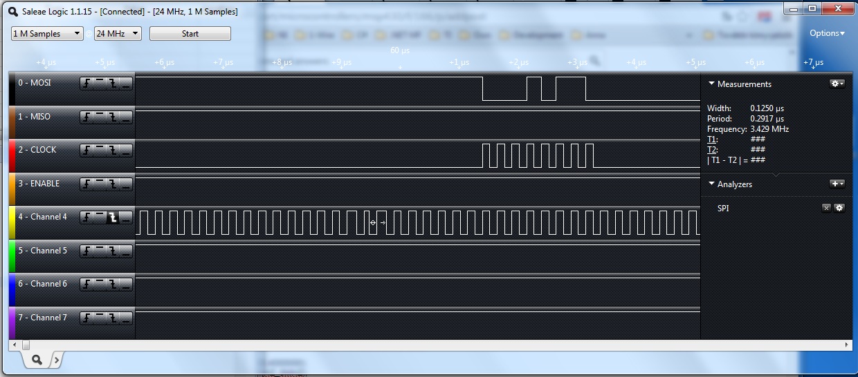
As you can see there are many clock phase don't match the requested 4Mhz. What is the reason of the inaccuracy? Is it? "4000 / 32.768 = 122.07" If I increase the clock speed to 16MHz this ratio will be 488,28. How does this "error" effect on the SPI clock? I mean, does the SPI communication stable and accurate despite of this error?
My second question is shall I use XT2 for FLLREF for DCO in order to get accurate 16Mhz clock signal?
Looking forward your kind reply,
