This thread has been locked.

If you have a related question, please click the "Ask a related question" button in the top right corner. The newly created question will be automatically linked to this question.

MSP430 LPM3 power consumption

Other Parts Discussed in Thread: MSP430G2553, MSP430WARE

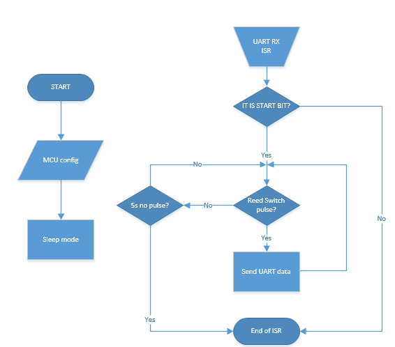
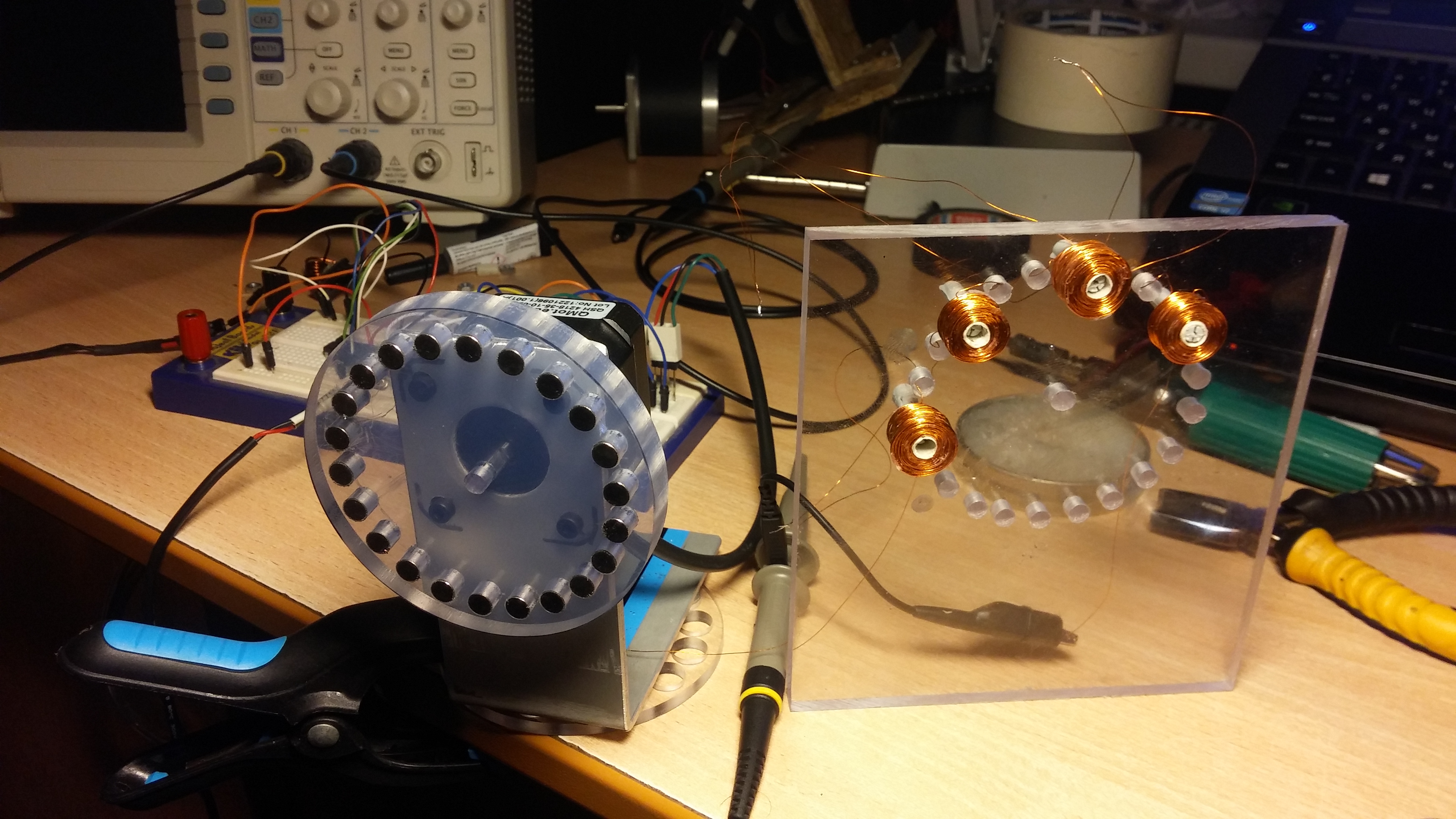
Hi all ! I'm doing "energy harvester" with wireless sensor node that includes msp430g2553 MCU. Trying to measure power consumtion, but no do not go for now. Using shunt resistor (1k 5%) i have got 345uA for active and 320uA for LPM3 mode. I thout that is something wrong here. Measured using multimeter - got almost the same results - 319uA for LMP3 mode ! Do not understand...It means that MCU do not go sleep ? Testing algorythm is : waiting for button press, then send some data using UART (150 in my code), after that go to sleep (LPM3) and wake up when UART RX or P1 BIT4 interrupt occures. Now everything is acting as is should, only current consumtion is very high in LPM3. Maybe someone can find mistake in my code. Thanks ! 

#include <stdio.h>
#include "serial.h"
#define LED0 BIT0
#define LED1 BIT6
#define RXD 0x02
#define TXD 0x04
#define PUSH 0x08


volatile unsigned int  run=0, sleep=0;

void main( void )
{
// Stop watchdog timer to prevent time out reset
WDTCTL = WDTPW + WDTHOLD;

uart_init(); //is header failo

P1DIR &=~PUSH; // Mygtukas kaip įėjimas BUTTON as INPUT
P1OUT |= PUSH;
P1REN |= PUSH; // Enables pullup resistor on button

P1DIR |= LED0;
P1DIR |= LED1;
P1OUT &= ~LED0; //pradine busena - off
P1OUT &= ~LED1;

P1IE |= BIT4; // igaliname P1.4 pertraukti interrupt fot P1 BIT4

UC0IE |= UCA0RXIE; // Enable USCI_A0 RX interrupt
__enable_interrupt();

while(1)
{

P1OUT|=LED1; // LED for indicating active mode

if((P1IN & PUSH)==!PUSH) { // Was button pressed? 
P1OUT ^=LED0 ;
run^=0xFF;
__delay_cycles(500000);
}

if (run==0xff) //START FLAG
{
//SENT DATA FOR RF MODULE

send_int(9); //duomenu nusistovejimui
__delay_cycles(23000);

send_int(1);
send_int(2);
__delay_cycles(23000);

sleep++; //counter for sleep mode

}
if (sleep>=150) { //go to sleep

P1OUT &= ~LED1; //LED1 OFF
P1OUT &= ~LED0; //LED0 OFF
sleep=0x00; //clear sleep mode counter
run=0x00; //clear start flag
_BIS_SR(LPM3_bits + GIE); //Go to LPM3 mode
}
} //while 
} //main 


//----------------------------------P1 BIT 4 interrupt -----------------------------------------

#pragma vector=PORT1_VECTOR
__interrupt void Port_1(void)
{
P1IFG &= ~BIT4; // P1.4 IFG cleared
P1IES &= ~BIT4; // toggle the interrupt edge,
_BIC_SR(LPM3_EXIT); // LPM3 WAKE UP
}
//----------------------------------UART RECEIVED interrupt---------------------------------------

#pragma vector=USCIAB0RX_VECTOR
__interrupt void USCI0RX_ISR(void)
{
if (UCA0RXBUF == '1')
{
//for future
}
_BIC_SR(LPM3_EXIT); // LPM3 WAKE UP
}

  • One thing stands out immediately: _BIC_SR(LPM3_EXIT);

    It's probably not causing the high power consumption, but it's worth fixing as it can cause other problems. See this thread for more information: Problem with _BIC_SR(LPM3_EXIT);

    Out of interest, are you measuring current consumption with the code launched from the debugger, or have you programmed the flash, detached the debugger and reset the MCU?

  • Programmed flash, removed all jumpers to emulation board, and with power supply 3.3V into VCC. Like that : 

    When measuring no jumpers to LED also.

  • I like to measure on the high side as having 1K on ground can not be good as gnd should always be the least path of resistance.

    the Launchpad makes it easy to measure high-side, the Vcc jumper will be replaced with two leads going to Multi-Meter.
    All other jumpers need to be removed, is the pcb reversion using external pull-up resistor on P1.3? (I think some older version did?)

    Are all unused pin set with pull resistor enabled, in pull-down mode preferable.
    Even Port3, though not reaching outside on the 20pin version of G2553 it (may?) internally still be floating.

    As C  hides what is really done by using intrinsic, in Main code you write directly to SR

    in IRQ you need to modify the value it have on the stack, as when a IRQ exits it writes this value back to SR.
    That is all done in hardware  and you can not change hardware, but you can "trick" what value it thought it had when it entered in to the IRQ.

    __bic_SR_register_on_exit(LPM3_bits)

    And if you where not in LMP3 mode to start out with , nothing bad will happen as bic is like ANDN

  • A good starting point might be \msp430ware_1_97_00_47\examples\devices\2xx\MSP430G2xx3_Code_Examples\Assembly_CCS\msp430g2xx3_lpm3.asm

    which advertises "Demo for measuring LPM3 current:"

    ;   MSP430G2xx3 Demo - Basic Clock, LPM3 Using WDT ISR, 32kHz ACLK
    ;
    ;   Description: This program operates MSP430 normally in LPM3, pulsing P1.0
    ;   at 4 second intervals. WDT ISR used to wake-up system. All I/O configured
    ;   as low outputs to eliminate floating inputs. Current consumption does
    ;   increase when LED is powered on P1.0. Demo for measuring LPM3 current.
    ;   ACLK = LFXT1/4 = 32768/4, MCLK = SMCLK = default DCO
    ;   //* External watch crystal installed on XIN XOUT is required for ACLK *//

    From there, look for similar C code and build your project from the example...


  • Million thanks to you ! Replaced _BIS_SR(LPM3_bits + GIE); into LMP3; and _BIC_SR(LPM3_EXIT); into LPM3_EXIT; and now i have 340uA in active mode and 4uA in LMP3 mode! As Tony Phillips mentioned i need to properly set-up unused pins. Another question. I need send RF data 4-8 times in a second. If MCU will go into LPM3 after every data packet (as i said 4-8 times), this will help with energy saving, or not?
  • A msp430 should be used in state-machine way with IRQs triggering short burst of data to be
    processed and sent to other IRQ based routines like USCI.
    So always sleep using LMP3 and that way you don't even need to use while() or until() as that waste energy.
    C does not help you write code this way as it was never custom made for msp430 and its IRQ based architecture.
    But I will some day release a micro-RTOS for the msp430 that does all that for you, with a syntax closer to F# & Parallax Spin

  • Whole system should work like this - MSP waiting for start signal from other RF module (LPM3 mode + UART ISR ? ) . When MSP got that signal, then it should send signal every time when P1 bit4 goes high (reed switch input) (ACTIVE MODE ?? ). Reed switch send signals 4-8 times in a sec. If there are no signal for 5s, then go sleep and wait for UART start signal. If there are no uart start signal, mcu should not react into reed switch input. This is imaginary algorithm :

    I agree that I can program everything without while() and delay() functions, insteed delay i can use timers, and everything else do with ISR what i'm doing now in while(1) . Can i check uart received data in uart ISR in LPM3 mode, or MCU should wake up, and then check ?

  • No one uses reed switch anymore. Is it motion or magnetism you are looking for?
    They make devises that uses 5uA, that check the status around 20/sec.

    Most external modules have a FLAG pin (mostly called IRQ) to signal that there is data to read.
    If this device sends data out without it, the G2553 USCI in uart mode will wait in lpm3 mode and wake you up when a byte have come in.

  • You see, there is rotating disk with magnets ( 8 magnets). If disk spining 1 rotation per second, i need send 8 data packets. So what i should use to catch magnet insteed of reed switch?

  • I use this one, best part is the sensoring is on the gables and not the top, if that is what you are looking for.
    www.mouser.com/.../MRMS201A

    But they make many different ones, you want omnipolar as others only toggles when S-pole to N-pole have occurred etc
    www.mouser.com/.../N-6g7qoZscv7

    this is one through hole so you can bend it how you want it:

    http://www.mouser.com/ProductDetail/Diodes-Incorporated/AH180-PG-B/?qs=sGAEpiMZZMvhQj7WZhFIAMy3TNn8eml8dOZMS8Mjkcc%3d

  • I saw these parts before. I choosen reed switches because they are passive element. Every uA is important to me..

  • SM351LT: Average current of 360 nA typ
    If you worrying about 0.4uA, wait until you software and pcb design due to you not being an expert designer yet consumes 20uA all the time.
    Battery self-discharge by itself is around 5uA if it has protection circuit, like lipo's do.
  • Ok then.. I have system like that :

    Now system works like generator (when coils are in front of magnets) . I want attach something between coils that will help to detect rotation direction of magnets. Air gap between magnets (neodynium n50) and coils is 1-2mm. You mensioned SM351LT, i read that is very sensitive device. Magnetic field created by the coil does not activate SM351LT ?  I need to get 2 sequences of pulses, whick i can decode and detect direction. This is my imagination using reed switches:

**Attention** This is a public forum