This thread has been locked.

If you have a related question, please click the "Ask a related question" button in the top right corner. The newly created question will be automatically linked to this question.

USCI UART on MSP430G2553

Other Parts Discussed in Thread: MSP430G2553

Hi,

I am trying to learn the UART communications on MSP430G2553 and beginner. Please answer the following questions of me

1. Can UART communication be done through the default USB connection to emulator or is it necessary to use RS232 to USB converter ? Several blogs suggested USB emulator connection is sufficient for UART. If yes, please explain USB emulator connection works for UART.

2. Assuming USB emulator connection works, I tried using hyperterminal for windows 7. I can see MSP430 assigned COM13 port in device manager but however I am not able to establish connection in hyperterminal. I tried using Putty but I wasnt able to open after giving serial port settings. 

3. Below is the my code for Transmitting data.


#include <msp430.h>

/*
* main.c
*/

char message[6]="Hello";
void config_UART(void);
void config_clock(void);

int main(void) {

unsigned int i;

WDTCTL = WDTPW | WDTHOLD;              // Stop watchdog timer

config_clock();

config_UART();

_EINT();                                                        //Enable Global Interrupt Bit

UCA0CTL1=UCA0CTL1 & 0xFE;              //Enable UART Operation

IE2 = 0x2;                                                    //Enable Tx Interrupt

for(i=0;message[i]!='\n';i++)
{
UCA0TXBUF=message[i];                       //Fill Buffer with Data
while(IFG2 & 0x02==1);                          //Wait till the data transmitted.
}


}

void config_clock(void)
{
BCSCTL1=CALBC1_1MHZ;                      //Setting clock of 1 MHz.
DCOCTL=CALDCO_1MHZ;

}

void config_UART(void)
{
UCA0CTL0=0x00;                                      //Settings for Standard UART communications.
UCA0CTL1=0XC1;                                   //Selecting SMCLK as source for UART clock
UCA0BR0=0x68;                                      // Baudrate 9600 settings at clock of 1 MHz
UCA0BR1=0x00;
P1SEL=0x06;                                             // Configuring Ports for UART Tx and Rx operation
P1SEL2=0x06;

}


#pragma vector=USCIAB0TX_VECTOR
__interrupt void UART_TX(void)
{

}

I feel I dont understand the working of Tx Interrupt flag and feel my logic is not correct after transmitting data(the one with while loop). Please explain me how TxIFG flag is set or reset when data is written to TxBuffer. As of now, i feel TxIFG flag is reset when data is transmitted and is set when data is written to buffer. With the above code, its always struck in the ISR and doesnt come out. 

Thanks and regards,

Shivakumar

  • shivakumar wantamutte said:

    I am trying to learn the UART communications on MSP430G2553 and beginner. Please answer the following questions of me

     Instead of these request wasting time on both side why not read launchpad user manual then follow lab workspace created just to teach how to use MSP peripheral?

     Your code use interrupt but service is empty so try learn from online teaching labs, all is on launchpad user manual, have you read it?

  • Hi..
    Yes, I have read it but could not understand about the TxIFG flag working. I was trying to making the flag to zero in ISR, but somehow while posting it got deleted. If possible please clarify my doubts.
  • Hi Robert,
    If I haven't read the manual then I would not have written those lines of code on UART .
  • USCI is buffered (unlike its smaller USI version)

    The TxIFG is set when the buffer is ready to take a new byte,
    as it just transferred the byte it had to the hardware serializer stage.

    When you write a new byte the TXbuff the  TxIFG flag is cleared, so you can exit IRQ without triggering a new IRQ.

  • shivakumar wantamutte said:
    ... I have read it but could not understand about the TxIFG flag working...

    If you do not understand it, you could avoid using it. For 9600 b/s, a delay of 1042 uSec will do the trick.

    #include <msp430.h>
    /*
    * main.c
    */
    char message[]="Hello!\r\n";            // !!! !!! null terminated string
    void config_UART(void);
    void config_clock(void);
    int main(void)
    {
      unsigned int i;
      WDTCTL = WDTPW | WDTHOLD;             // Stop watchdog timer
      config_clock();
      config_UART();
    // !!! !!!  _EINT();                              //Enable Global Interrupt Bit
      UCA0CTL1=UCA0CTL1 & 0xFE;             //Enable UART Operation
    // !!! !!!  IE2 = 0x2;                            //Enable Tx Interrupt
      while (1)                             // !!! !!! repeat forever
      {
        for(i=0;message[i]!=0;i++)          // !!! !!!
        {
          __delay_cycles(1080);             // !!! !!! Wait till TXBUF ready
          UCA0TXBUF=message[i];             //Fill Buffer with Data
        }
      }
    }
    void config_clock(void)
    {
      BCSCTL1=CALBC1_1MHZ;                      //Setting clock of 1 MHz.
      DCOCTL=CALDCO_1MHZ;
    }
    void config_UART(void)
    {
      UCA0CTL0=0x00;                                      //Settings for Standard UART communications.
      UCA0CTL1=0XC1;                                   //Selecting SMCLK as source for UART clock
      UCA0BR0=0x68;                                      // Baudrate 9600 settings at clock of 1 MHz
      UCA0BR1=0x00;
      P1SEL=0x06;                                             // Configuring Ports for UART Tx and Rx operation
      P1SEL2=0x06;
    }
    /* !!! !!!
    #pragma vector=USCIAB0TX_VECTOR
    __interrupt void UART_TX(void)
    {
    }
    !!! !!! */

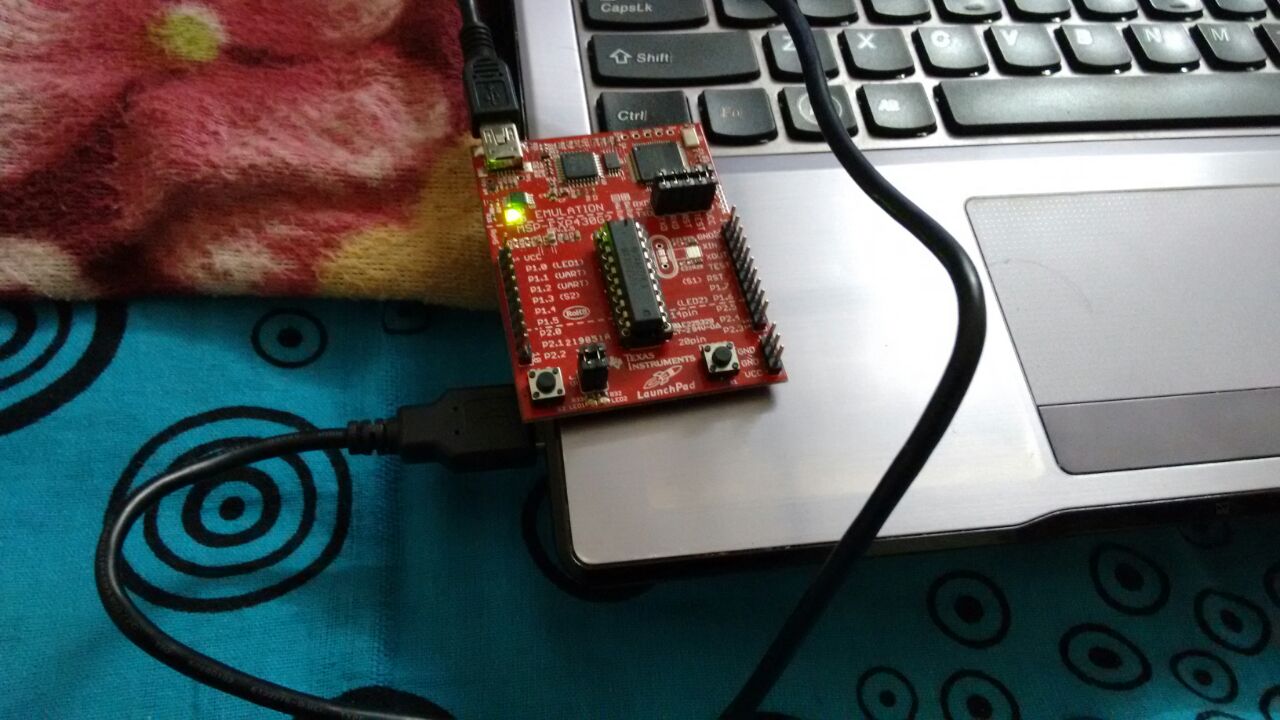
  • Thanks for the reply. But I don't see any message received. I have attached the image of launchpad interface to host pc. I believe this is the only connection, I, need to make it to work. Please let me know if I am doing it wrong or any other thing.

  • If you're using USCI via the USB connection the TX/RX jumpers on the launchpad need to be pointing left/right instead of up/down. If you look at the area between the word "EMULATION" and the jumper block (just above the target MCU) there's a diagram. You need to make the jumpers match the "HW UART" diagram.

**Attention** This is a public forum