This thread has been locked.

If you have a related question, please click the "Ask a related question" button in the top right corner. The newly created question will be automatically linked to this question.

MSP430 SPI MOSI Problem

Other Parts Discussed in Thread: MSP430F2274, ADS1298

Hi all,

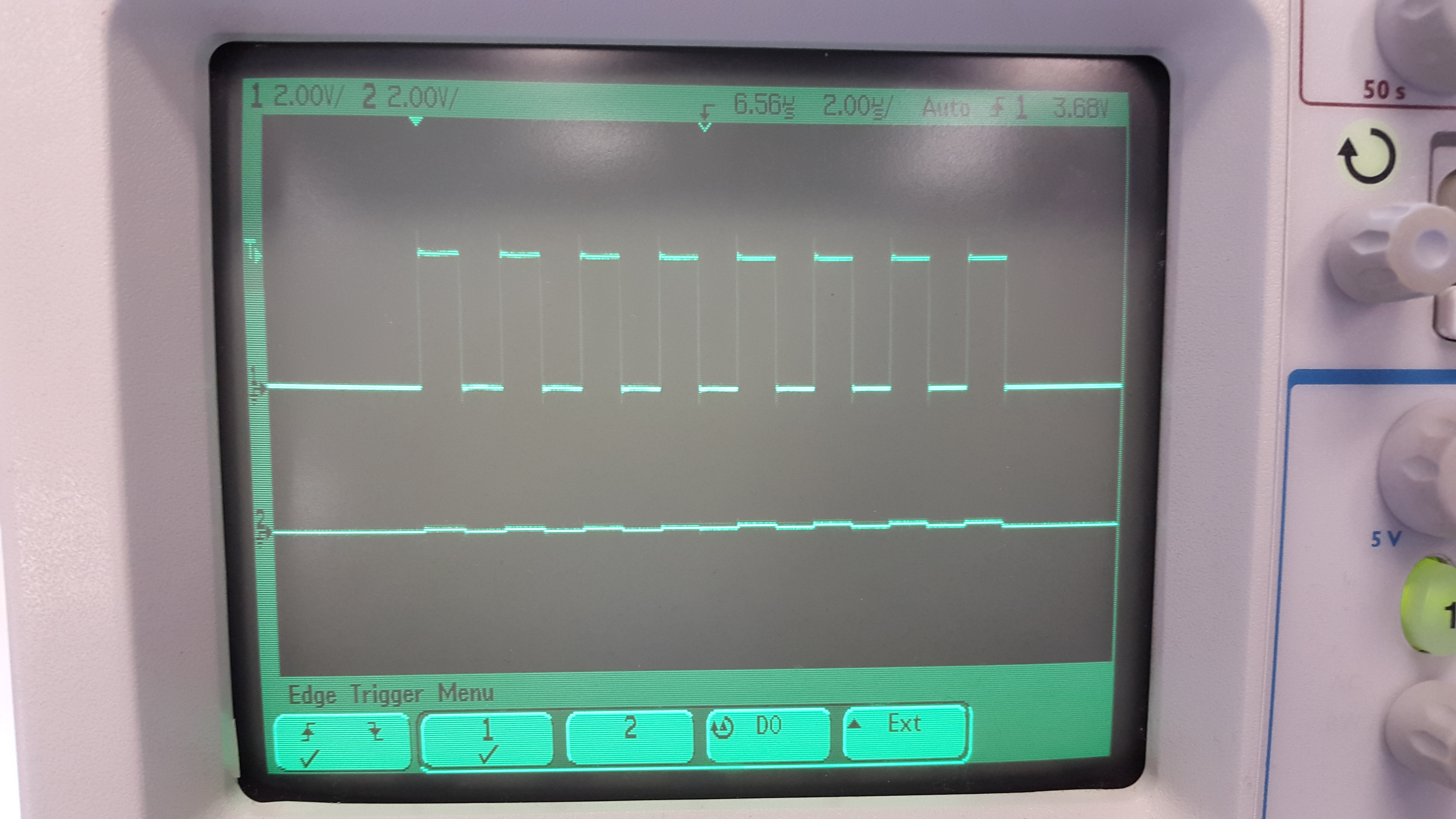
I am currently having problem sending SPI MOSI data output from eZ430-RF2500 (MSP430F2274). I have checked the Clock and CS output is correct. But, the problem is the output of MOSI always in the range of 220mV, which is very small. 

Basically, I just need to investigate the output of the SPI. Can anyone help me what is wrong with my code?

Note: CLOCK pin connected to channel 1 oscilloscope, MOSI pin connected to channel 2 oscilloscope. CS and MISO are floating.

#include <msp430f2274.h>

int main(void) {
volatile unsigned int i;
unsigned char x;

WDTCTL = WDTPW + WDTHOLD; // Stop watchdog timer
P3SEL |= 0x0C; // P3.3,2 USCI_B0 option select
P3DIR |= 0x01; // P3.0 output direction

DCOCTL |= DCO1;
BCSCTL1|= RSEL0;

UCB0CTL0 |= UCMSB + UCMST + UCSYNC; // 3-pin, 8-bit SPI mstr, MSB 1st
UCB0CTL1 |= UCSSEL_2; // SMCLK
UCB0BR0 = 0x02;
UCB0BR1 = 0;
UCB0CTL1 &= ~UCSWRST; // **Initialize USCI state machine**

while(1)
{
P3OUT &= ~0x01; // /CS reset

while (!(IFG2 & UCB0TXIFG)); //
UCB0TXBUF = 0xFF; //
x = UCB0RXBUF; // data = 00|DATA

P3OUT |= 0x01; // /CS set

for(i=0;i<20;i++);
}


}

  • As you are following the msp430x22x4_uscib0_spi_01.c example
    double check that channel2 is on SIMO

    try UCB0TXBUF = 0x5A; //
    To see if it moves, as you are sending 0xff and depending on sync/phase maybe it could be inverted = all zeros

    if still not moving, would guess there is a short on the pcb, do //P3SEL |= 0x0C and measure the resistance on this trace.
    Is the MOSI trace connected to wrong pin on slave and it's an acctual output?

  • I have tried to send UCB0TXBUF = 0x00, 0xF0, 0xAA and the output are the same.

    I have tested my PCB as well, there wasn't any shorted. Also P3SEL |= 0x0C has been written in the code above as well.

    This microcontroller www.ti.com/.../ez430-rf2500 will be used to communicate with ADS1298. At the moment I'm just going to investigate the output of the SPI. Is the code above for basic SPI should work?
  • Try this to see if P3.2 cycle at a few 100Khz
    Move the probe to some adjoining pins as you may have it hocked up at the wrong spot.
     
    //P3SEL |= 0x0C; // P3.3,2 USCI_B0 option select
    P3DIR |= BIT0+BIT2; // P3.0,2 output direction
    while(1)
    {
    P3OUT ^=BIT2
    }

  • I finally found the problem. P3SEL should be 0x0E. The TI example code miss the BIT0.
    Now, I can send the SPI data via UCB0TXBUF.


    I have another problem right now. I am actually programming ADS1298 using my self-made board via SPI. But, the problem is, I keep getting the data receive to my MSP430 0x0F.
    I tried to solve this problem by testing the MSP430 SOMI pin, and the ADS1298 which has to be connected to MSP430 separately.

    The ADS1298 sending the correct data, but the MSP430 seems like it always output 0x0F which should be input from the ADS1298. Do you know what is the problem with my MSP430 SIMO?

    Thank you!
  • It might be a wiring problem. Double-check your schematics. Or a bad soldering on the MSPs SOMI
    Or the SOMI pin is not selected.

    One thing I noticed in your code: you write to TXBUF and then read RXBUF. This won't work. Writing to TXBUF means the USCI starts sending (or is maybe still sending the previous byte, as TXBUF is a 1-byte FIFO), but hasn't received anything yet. Wait until the USCI signals reception of a byte by setting UCRXIFG.

**Attention** This is a public forum