This thread has been locked.

If you have a related question, please click the "Ask a related question" button in the top right corner. The newly created question will be automatically linked to this question.

MSP430F2410 4-wire JTAG error

Other Parts Discussed in Thread: MSP430F2410

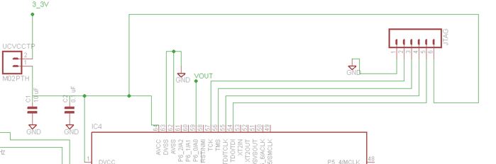
I am using a board created by my hardware engineer, trying to use 4-wire JTAG to program the uC. I am getting the MSP430: Error Connecting to the target: unknown device problem. I will attach the schematic.


We are just using the 4 JTAG pins, power, and ground as we could not find a JTAG connector for eagle cad in time to incorporate into this version of the board.

I have the power pin connected to our 3.3 V line, ground is connected to AVss, and I believe the other four pins are connected correctly.

Can anyone see a reason why I am getting this error?

It is my understanding that for the F2410, I don't need the RST connection because 2-wire JTAG is not compatible.

Thank you in advance for any help.

  • You’re correct, RST doesn’t need to be connected.

    I understand you power the MCU from JTAG and you are sure to have this connected to pin 2 from JTAG and the device get’s 3.3V?

    Your JTAG flat cable connection is not longer than 150mm?

  • We are actually powering the MCU from a battery, so we have the 3.3 V connected to pin 4 of the JTAG.

    The cable is the one that came with the FET, looks to be about 8 inches long. Would that length cause an issue?

  • You must add a 30k pull-up resistor at the nRST pin. It is prudent to add a small high-frequency capacitor from nRST to ground too.
  • Kevin Erskine said:
    We are actually powering the MCU from a battery, so we have the 3.3 V connected to pin 4 of the JTAG.

    Is Ok.

    Kevin Erskine said:
    The cable is the one that came with the FET, looks to be about 8 inches long. Would that length cause an issue?

    How do you do that, the original cable is 14p you are using 6p?

    And of course OCY RST recommendation (and I guess that will be your problem).

  • Thank you. So to make sure I understand correctly, even though we don't need to connect the nRST to anything, we still need it to be at a high level, hence a pull up resistor, which would just be 3.3v -> 30k -> nRST ?

  • Correct, our board doesn't have a JTAG connector, just header pins for the lines we thought would be necessary. We did not put one for the nRST pin but now it looks like we need to.
  • While RST does not need to be connected, it should. So the debugger can reset the target before uploading a new firmware. Else the CPU could be in a state where it cannot attach.
    Also, I remember reading that on latest IDEs, using SBW is the default, which requires access to RST line (does the 2410 support SBW?)
  • Jens-Michael Gross said:
    While RST does not need to be connected, it should. So the debugger can reset the target before uploading a new firmware. Else the CPU could be in a state where it cannot attach.
    Also, I remember reading that on latest IDEs, using SBW is the default, which requires access to RST line (does the 2410 support SBW?)

    FET will reset target device by JTAG sequence, without using RESET pin. MSP430F2410 does not support SBW, so RESET connection with FET is not needed.
  • "FET will reset target device by JTAG sequence"
    If, and only if, the MSP is still responsive. If the CPU has crashed, JTAG probably won't work reliably.
    There is a reason why the Elprotronic tool offers three different ways to reset the target: by RST, by JTAG or by power cycle (if supplied by the FET). And uses all three by default.

**Attention** This is a public forum