This thread has been locked.

If you have a related question, please click the "Ask a related question" button in the top right corner. The newly created question will be automatically linked to this question.

Distorted Signal using PWM for DAC on MSP430 Launchpad

Other Parts Discussed in Thread: MSP430G2553, MSP430WARE

Hey everyone,

I'm working on a project that simulates a heart rate signal using the MSP430G2553, which is right now on the Launchpad. I'll try to explain everything I've done and what problems I'm having so I can get any help from you all.

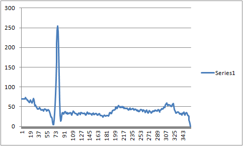
I am using previous patients data that is available online from an MIT-BIH database. Because of the limited flash on the MSP430, I'm trying to just repeat a 1 second signal which has 360 data points. These values range from -0.535mV to 0.84mV. I don't actually need to output that small of data, since my output signal will later be going through an Analog Front End to with filters and opamps to make it the desired amplitude. I just need the shape of the signal to match the data. So, I am scaling the data. The scaling factor is using this equation S = (2^n - 1)/(Max - Min), where n = 8 and that is used to scale each data point using this equation newValue = S*(data - Min). Then I just round the data to get rid of the decimal and end up with data between 0 and 256. So that's the data. When I graph these points in Excel, it looks correct, as shown here.

After I output the signal from P1.0, it goes through a filter

to see the analog output from the PWM signal. That is just an excerpt of the signal, but that's where I'm measuring it from right now. On an oscilloscope, this then gets distorted to look like this. The main issue I'm having is how large those two used to be small humps have become. I understand the chop in the signal since the repeating part doesn't match up nicely.

The program I am using was modified from the popular Simple DAC using PWM method found online. I'll paste the code.

I know this is a lot of information and a long post, but if anybody is able to just look through it, I would be very grateful. The main questions I have are 

1) Does anybody have any insight into why those two bumps are so much larger than the excel graph or maybe why the peak isn't as large in comparison?
2) Also, since I'm using 256 PWM widths, my frequency is very fast. To make it more realistic, how would I go about increasing the frequency of the initial timer to output a much higher frequency signal without changing the shape of the signal.

Thank you all very much.

#include <msp430g2553.h>

unsigned char counter;				// Current location in wave array

unsigned char wave[360] = {
		69,
		69,
		69,
		69,
		69,
		69,
		69,
		69,
		74,
		71,
		69,
		.
		.
		. //keeps going
};

unsigned int i;						// Used for 'for' loops.

void main(void)
{
	WDTCTL = WDTPW + WDTHOLD;					// Stop WDT

	P1DIR |= BIT0;								// P1.0 output
	counter = 0;								// Reset counter

	// Initialize Timer
	CCTL0 = CCIE;								// CCR0 interrupt enabled
	CCTL1 = CCIE;								// CCR1 interrupt enabled
	CCR0 = 256;									// Set PWM period to 256 clock ticks
	CCR1 = wave[counter];						// Set first duty cycle value
	TACTL = TASSEL_2 + MC_1 + TAIE + TACLR;		// SMCLK, upmode, enable interrupt, clear TA1R

	_BIS_SR(LPM0_bits + GIE);					// Enter LPM0 w/ interrupt
}

/**
 * TimerA0 interrupt service routine
 **/
#pragma vector=TIMER0_A0_VECTOR
__interrupt void TIMER0_ISR(void)
{
	P1OUT |= BIT0;				// Set P1.0
	
	CCR1 = wave[counter];		// Set next duty cycle value
	counter += 1;				// Add Offset to CCR0
	if ( counter == 360)			// If counter is at the end of the array
	{
		counter = 0;			// Reset counter
	}
}

/**
 * TimerA1 Interrupt Vector (TAIV) handler
 **/
#pragma vector=TIMER0_A1_VECTOR
__interrupt void TIMER1_ISR(void)
{
	switch( TAIV )
	{
		case  2:				// CCR1 interrupt
			P1OUT &= ~BIT0;		// Clear P1.0 to determine duty cycle.
			break;
		default:
			break;
	}
}

  • Jeffrey,


    First you set TAIE to enable timer overflow but you are not using it, this is waist of capacity.


    Maybe this setup can work (apparently not) I would do this on a different way.

    You have two timers, I would use both but it is possible with one depending on PWM frequency and step interval.

    One timer to generate the PWM-DAC and a second with a (much) lower frequency to step trough your array on the required interval time.

    The PWM timer gets the duty and can be outputted directly to the port pin.


    I don’t know if you have a resistor between the port pin and your filter input AN_0, if not you must add one or remove the first capacitor. The size of the resistor and the capacitor depends on the PWM frequency and the required output ripple.


    Leo.

  • Hi Leo,

    Thank you for your response. I am going to try to just use one of the timers. I may need the other timer later in the project since I am planning on using an external SD card to read in more than just one second of data to the MSP430 so I don't get the break between signals.

    For the filter portion, that is just a portion of the entire circuit that I am using. But yes, I am showing the signal from the oscilloscope as coming from after that 20kohm R15 resistor.

    For me to slow down the output signal though, for example as shown in the oscilloscope, there is approximately one period of the heart rate signal every 65 milliseconds. I want to be able to slow down the signal so that it will be like one period of the heart rate signal every 1 second or half second so it's more realistic to a humans heart rate bpm. Is there not a way to perhaps slow down the clock speed of the MSP430 to accomplish this task? Or perhaps, repeat each value in the array multiple times so it appears to be a more realistic speed?

    Also, that is just half of the problem I am having. Do you have any insight into why certain amplitudes of the signal do not match the corresponding amplitudes of that which was graphed using Excel?

    Thank you.
  • I don’t think your current way can’t work at all. And at least to convert the PWM to a DAC you must output the PWM to a RC combination, that’s why you need to remove the first capacitor.

    Setup the timer as follows;

    Timer clock = SMCLK = 1MHz

    Timer clock divider (DIV) = 8

    Timer Up-mode (1)

    CCR0 = 255

    This gives a PWM of ~12.2KHz

    CCR1 = Duty

    Output TA0.1 (CCR1) to P1.2 Mode Reset/Set (7), this is the PWM

    Enable (only) CCR0 interrupt

    Create a unsigned integer variable –Interval- to hold the step interval time (time base)

    In the timer ISR you decrement the Interval variable with one. If Zero you increment your ‘counter’ and update CCR1, and preset Interval.

    Interval = 6120 = ~500mS, 12240 = ~1Sec

  • As you only have TA (and not TB) I think the problem could be that you are missing the window as the ISR can't finish in time if the values are below 50 and you are using DIV1 for the Clock. (so slow it down with DIV4 or 8)
    256 data points and using 8bit counter so you don't have to use compare and reset counter, saves a lot of cycles as it wrap around naturally.
    Oversampling will help slowing down the heart beat and improving smoothness. e.g use the same value 8 times before you step to next one.

  • Oops little mistake; You need to divide 6120 with the number of samples/hart rate, 6120/360=17.
  • Hi Tony,

    Thank you for your response. I feel like maybe you are on the right track since it seems to be having most of the problems during the lower values. But I am having trouble understanding what you mean. How do I go about slowing down the clock with a clock divider of 4 or 8? Is that just one line of code that I would add and where would I put this?

    Addressing your next statement about the 256 data points and using an 8 bit counter, there are actually 360 data points for one second of the signal. So I don't think that would apply in my situation.

    I understand the oversampling method, but this would only work if I had more flash since I can't really add much more data to the array and have it still be able to run. I will be trying to implement an SD card in this project so that I could read perhaps 10 seconds of data or more and have it just repeat that in the long run. But the SD card seems very complicated, even just for reading from, so I am trying to figure out a way to slow down the clock and get it all working before trying on the SD card.
  • Oops again (it’s too late for me). I was calculating with the wrong SMCLK frequency.
    Timer clock = SMCLK = DCOCLK = 16MHz.
    Timer divider (DIV) = 4, PWM is ~15.7KHz.
    Interval = (7843/360) = ~500mS/hart rate cycle.
    You also need to change your capacitor to ~22nF (and R=20K) to get best analogue output.
  • And BTW, reading Tony’s post, your counter is a ‘char’ you will never reach 360, max is 255. Make it an integer!
  • A slower PWM over all, will assure that you don't miss the lower values. if the mclk is 1MHz but the TA0 is at 256KHz the ISR will finish in time.
    The signal will be a little rougher but with higher resistor values should be OK
    Or could just use higher values to start with and attenuate the signal with a weak pull-down resistor.

    If you can re-sample the data so the length you want fits in 256bytes, it saves cycles.
    The compiler should create something like this:
    mov.b &counter, R12
    mov.b table(R12), &CCR1
    add.b #1, &counter
    reti

    After the add.b, if you don't have to cmp.w to 360 and reset to zero, saves 6-8 cycles.

    Dedicating the R4 (as C does allow that) to point to table and putting the table at a 512byte boundary,
    will be the fastest possible routine.
    mov.b @R4+, &CCR1
    bic.w #BIT8, R4 // force R4 to auto wrap around (works with 256,512 and 1024 tables too)
    reti

    Oversampling:
    it's a waste to put 8 times more data in flash, so if you could make it re-use the same spot in the table 8 times.
    The way to add 1 to the table-counter every 8th time, would need to be fast too.
    dec.b R5
    jnz exit
    mov.b #8,R5 // 8 is a "fast" value
    mov.b @R4+, &CCR1
    bic.w #BIT8, R4 // force R4 to auto wrap around (works with 256,512 and 1024 tables too)
    exit: reti

    Or alternative use emulated fixed-decimal-point for 4x oversampling

    mov.w &counter, R12
    rra.w R12                           // div by 2 (don't use values above 32K as msb->msb)
    rra.w R12                           // div by 2 again
    mov.b table(R12), &CCR1
    add.w #1, &counter
    bic.w #BITA, &counter   // wrap around table size *4
    reti

  • Thanks so much Leo.

    I am still looking into your previous responses and will be able to modify code and test on an oscilloscope tomorrow. I understand what you are trying to do with decrementing the interval variable and at that point I would increment the counter and update CCR1. I have a few questions though.

    1) In setting up the timer, can I do this in just like a line or two of code? Something like this:
    TACTL = TASSEL_2 + MC_1. That sets the timer to SMCLK and Upmode(1), right? But how do I actually set the clock speed to 16Mhz like you said or that is what the default is.
    2) How do I set this clock divider? Tony mentioned changing the divider as well. Is this just one line of code where I set it?
    3) Does CCR1 for the duty cycle have to be output to P1.2? What is it set to right now since I never specified anything previously in my code?
    4) I think the only other question I have is how do I enable (only) CCR0 interrupt?

    5) If I already plan on having a few push buttons hooked up and am going to be using pins 1.1 and 1.2 for the buttons, will that mean that I won't be able to use those timers that you mentioned or even any of the ones that I have been using already in my code before any of these questions? Could pin 2.6 work since that one says TA0.1 or none of this would be possible?
  • First, if you are using CCS and have not installed MSP430Ware, in CCS select ‘View\CCS App Center’ and install ‘MSP430Ware’, this contains a lot of handy examples.

    Jeffrey Frye said:
    1) In setting up the timer, can I do this in just like a line or two of code? Something like this:
    TACTL = TASSEL_2 + MC_1. That sets the timer to SMCLK and Upmode(1), right? But how do I actually set the clock speed to 16Mhz like you said or that is what the default is.
    2) How do I set this clock divider? Tony mentioned changing the divider as well. Is this just one line of code where I set it?

    Yes this can be done at ones, but it’s preferable to use: “TACTL = TASSEL_2 | MC_1 | TACLR”, ‘|’ instead of ‘+’ is less catastrophic when a mistake. In the same line you can add the divider (DIV) bits ‘ID_2’ (=/4).


    For the clock; DCOCTL = 0; BCSCTL1 = CALBC1_16MHZ; DCOCTL = CALDCO_16MHZ;.

    Connecting the timer modules output directly to the port pin saves code and CPU recourses. You can use any pin which has TA0.1 capabilities. To select the module output: P2SEL |= BIT6;. At nearly the end of the Data Sheet you can find all the port functions under ‘Port Schematics’.

    Enable (IE) only the bit; CCTL0 = CCIE; and not in CCTL1 and TACTL (TAIE). And use only ‘TIMER0_A0_VECTOR’ ISR. Keep the ISR as fast as possible. There are ways to optimize it for speed but that’s for later.

  • " I feel like maybe you are on the right track since it seems to be having most of the problems during the lower values. But I am having trouble understanding what you mean."

    You update the duty cycle at the timer overflow interrupt. However, while your ISR is started and advances to the point where you write to CCR1, it may be that the timer has already advanced past the new trigger point. In this case you have a full timer cycle where the output doesn't change at all. TimerB allows synchronizing the CCR update with the timer overflow, but for TimerA, there is no fix.
    Using DMA instead of an ISR will help, but if MCLK is in the same range ad the timer clock, it is not a perfect solution.
    However, in any case, you can't have 0% and 100% DC. Both are illegal values(both would trigger rising and falling output at the same timer tick). Depending on 'polarity' of the PWM, one or the other can be done, but not both. The other one is an exception and needs to be separately handled by manually setting the pin output. Not possible with DMA, and adding execution time (and increasing the initial problem) in interrupt mode.

**Attention** This is a public forum