This thread has been locked.

If you have a related question, please click the "Ask a related question" button in the top right corner. The newly created question will be automatically linked to this question.

Unwanted Spike in PWM Singal

Hi All,

Could you please tell me why am I getting these spikes in the image below?

Here is the test code:

#include  <msp430g2553.h>

const unsigned int halfcycle[51] = {100, 108, 115, 122, 129, 135, 141, 146, 151, 154, 157, 159, 160, 160, 159, 157, 154, 151, 146, 141, 135, 129, 122, 115, 108, 100, 92, 85, 78, 71, 65, 59, 54, 49, 46, 43, 41, 40, 40, 41, 43, 46, 49, 54, 59, 65, 71, 78, 85, 92 };

signed int index = -1;
unsigned int comp = 0;


void main(void)
{
  WDTCTL = WDTPW + WDTHOLD;                 // Stop WDT

  //Calibrate DCO for 1MHz operation
  BCSCTL1 = CALBC1_1MHZ;
  DCOCTL = CALDCO_1MHZ;

  P2DIR |= BIT1 + BIT2;                            
  P2SEL |= BIT1;
  P2SEL &= ~(BIT2);

  P2OUT &= ~(BIT1+BIT2);


  TA1CCR0 = 200 - 1;                               
  TA1CCTL0 = CCIE;									// CCR0 interrupt
  TA1CCTL1 = OUTMOD_2 + CCIE;                         
  TA1CTL = TASSEL_2 + MC_3 + TACLR;                  // SMCLK, up-down mode

  _BIS_SR(LPM0_bits + GIE);                       // Enter LPM0

}


#pragma vector=TIMER1_A1_VECTOR						// ISR for CCR1 and CCR2 interrupts
__interrupt void Timer_A1 (void)
{
	switch (__even_in_range(TA1IV, 10))
	{
		case 0:											// no interrupt is pending
		{
			break;
		}
		case 2:											// CCR1
		{

			TA1CCR1 = halfcycle [index] - 1;
			break;
		}
		case 4:											// CCR2
		{
			break;
		}
		case 10:										// TA1IFG
		{
			break;
		}

	}

}


#pragma vector=TIMER1_A0_VECTOR						// ISR for CCR0
__interrupt void Timer_A0 (void)
{
	 index = index + 1;

	  if(index == 25)
	 {
		 index = 0;
		 P2SEL ^= (BIT1 + BIT2);

	 }
}

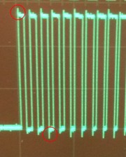
  • Are you referring to those spikes?, that is normal as those are over and under shoots.
    electricity flows like water and don't like to stop on a dime when something is filled up.
    Do you have any load on this test circuit?  as a mosfets capacitance will probably help a little  could also put a 20 ohm series resistor if it annoys you.

    Or are you referring to the noise in between the pwm?, if the trace is next to the active pwm trace it will pick up some stray electricity,
    though the trace is connected to ground due to DIR=1 and OUT=0 but unless it's a very short distance to gnd it will pick up stray signals. 
    but once it's under some type of load it should go away too (separate the traces with ground in between)

  • Okay! So can't get rid of these little spikes?! The spikes are not only those you mentioned but its there when there is no signal at all on the MSP430 pins (as shown in the original image).

    However, I am trying to implement an inverter with 24Vdc as input voltage. I am using unipolar spwm. Due to the spikes I am not getting my desired voltage at the inverter output.

    Thanks a lot for your quick reply and great help!

    Tahsina

  • A mostfet output would not be affected by those spikes on its input as that should be way above fully saturated anyway, e.g it's not voltage follower.
    But will of course create it's own over/under shoots from turning on and off its output.
    A inverters 24v/220v transformer will filter out pwm clipping, as it act as a large inductor coil.

  • those other spikes are apparently crosstalk from the line with a signal. If you don't have a capacitance or a load on a line, it will catch crosstalk.
    Remember: each wire is an inductor with 1/2 winding. Two of them build a transformer. A current change on one will induce a current on the other. And changing the voltage of one signal always results in some current, as there is always some parasitic capacitance to be filled.

**Attention** This is a public forum