This thread has been locked.

If you have a related question, please click the "Ask a related question" button in the top right corner. The newly created question will be automatically linked to this question.

getting DMA to work with SPI trigger

Other Parts Discussed in Thread: MSP430F5659

Hello,

I am trying to use the DMA to transceive data from the SPI of a MSP430F5659. There are several things I don't really understand, and its not working properly.

First of all I initialize the DMA2 to transmit data via USCIA1 by defining the apropriate trigger (21: USCIA1TXIF). Here's the sourcecode:

 void initDMA2(void)
 {
	/* reseting DMA for correct initializing */
	DMA2_RESET_STATE;
	/* setting USCIA1TX as a trigger for the DMA (AD7490) */
	DMACTL1 = 0
			| DMA2_TRIGGER_AD7490_USCIA1TX;
	/* configuring the DMA channel for use in AD7490 serial communication routine */
	DMA2CTL = 0 | DMASRCINCR0 | DMASRCBYTE | DMADSTBYTE
				| DMASRCINCR1 | DMALEVEL;
 }

i used some macros but they are working fine when iIcheck the registers (DMA2_RESET_STATE and DMA2_TRIGGER_AD7490_USCIA1TX).

as a next step I program the DMA2SA, DMA2DA and DMA2SZ :

/* creating pointer for SA */
	char command_buf[2] = {0};
	command_buf[0] = command_highByte;
	command_buf[1] = command_lowByte;

	DMA2_WRITE_AD7490_SA = (__SFR_FARPTR)command_buf[0]; 	/* set DMA source address */
	DMA2_WRITE_AD7490_DA = (__SFR_FARPTR)&UCA1TXBUF; /* set DMA destination address */
	DMA2_WRITE_AD7490_SZ = sizeof(command); 			/* bytes per transfer */
//	DMA2_WRITE_AD7490_CTL &= ~ DMAIFG; 			/* reset interrupt flag */
	DMA2_ACTIVATE_STATE;				/* start DMA */

	/* wait until DMA is finished */
	while (!(DMA2CTL & DMAIFG));

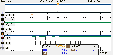
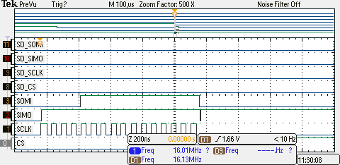
with this initialization it works but I send as a test two HIGH_BYTES as dummys but I don't see them on my scope. There's a differnt bit-pattern. So what is going wrong here?

Additional to my problem I don't know how to get the DMA -> USCIA1 running without using the DMALEVEL trigger, because the EDGE trigger only works with a low to high transition (user manual) but the USCIA1TXIF is set before something is written to the USCIA1TXBUF, so the trigger request is never reached except I use the DMALEVEL trigger but there the manual says it's only for external triggering via DMAE0.

For reception I tried to use another DMA channel to trigger on the USCIA1RXIF but this is also not working, clearly because my writing attempt is faulty.

could anyone help me with this?

best regards

Benni

  • I also modified my code to function with edge-triggered DMA, but i don't think this is good code, since i clear and set the UCIA1TXIF per software. It seems that the transfer works, but the first Byte is not what stands in my source address structure. I attach a photo from my scope so you cann see, that the first 8 bit are not what they should be, and i don't know why..i also stepped the routine and he just moves this false byte-package in the UCIA1TXBUF. The next one is correct..should be two times 0xF.


    please could anyone hewlp with this?

    here the code:

    /* creating pointer for SA */
    	char command_buf[2] = {0};
    	command_buf[0] = command_highByte;
    	command_buf[1] = command_lowByte;
    	UCA1IFG &= ~UCTXIFG;
    
    	DMA2_WRITE_AD7490_SA = &command_buf[0]; 	/* set DMA source address */
    	DMA2_WRITE_AD7490_DA = &UCA1TXBUF; /* set DMA destination address */
    	DMA2_WRITE_AD7490_SZ = sizeof(command); 			/* bytes per transfer */
    //	DMA2_WRITE_AD7490_CTL &= ~ DMAIFG; 			/* reset interrupt flag */
    	char temp = UCA1RXBUF;			// prevent UCIA1STAT_UCOE
    	DMA2_ACTIVATE_STATE;				/* start DMA */
    	UCA1IFG |= UCTXIFG;
    
    	/* wait until DMA is finished */
    	while (!(DMA2CTL & DMAIFG));

    and here the photo:


  • Hi Benjamin,

    I just had a quick look over your text (not the complete code) and I saw you were mentioning the already set USCIA1TXIF before writing a byte to it. You can clear this flag manually (or automatically clear it by writing to the TX buffer).

    Just from my mind now: Set the SZ to bytecount - 1, copy the buffer address + 1 to SA, enable the DMA and copy the first byte manually into the transmit buffer of the USCI which clears the IFG. The next rising edge will trigger the DMA. and go on copying the content of your buffer until SZ == 0 generates the IFG.

    Dennis

  • Hello Dennis,

    thanks for your post. In my second post I allready clear and set the UCA1TXIF manually, though your suggestion is a better way to implement the transfer, but why is the DMA sending some wrong code? And might that also be happening even if I send the first byte package manually? Like i wrote in my two posts, i don't understand why the DMA sends a different byte package than it used to send even though the content of the DMA2SA points to the direct valiue.

    I will try out your suggestion later when I'm back in the lab.
    Thanks again!

    best regards

    Benni 

  • Are your bytes correct when sending them completely without the DMA?

    Dennis
  • Are you sure the Source and Destinations addresses are set correct, you don’t show your macro’s.
    In your first post the Source address is wrong, in your second post is missing the 24-bit casting.
  • Indeed, the first expression misses the "&" for passing the address.

    Remember that you can pass the address of an array as follows:

    uint8_t array[10];
    
    uint8_t * array_pointer;
    
    array_pointer = array;
    
    // OR
    
    array_pointer = &array[0];

    And Leo is right with his statement concerning the casting. I don't know this one:

    (__SFR_FARPTR)anyaddress;

    I'm only used to these address assignments:

    __data16_write_addr( (unsigned short) &DMA2SA, (unsigned long) &command_buf[0] );
    __data16_write_addr( (unsigned short) &DMA2DA, (unsigned long) &UCA1TXBUF );

    Dennis

  • Maybe the typecasting is the problem..

    my macro is an expression for the low 16 bit of the lower DMASA register [ SFR_16BIT(DMA1SAL)]. In my first post the macro was only the DMASA and thats SFR_20bit ..so i searched for a right typecasting to point to a 8 bit address for my command struct:

    //#define SFR_20BIT(address)  extern volatile unsigned int address
    typedef void (* __SFR_FARPTR)();
    #define SFR_20BIT(address) extern __SFR_FARPTR address
    #define SFR_32BIT(address)  extern volatile unsigned long address
    
    #endif

    found that in the msp430f5659.h .
    Since i didn't know wether this was right or not I found a post of someone who wrote only to the lower 16 bit. But maybe exactly that is the problem, because the source address pointer expects a 20-bit address and i don't know where the other 4-bit are pointing at. So when i understand you right I should find the 20-bit address write function and use it for the correct assignment, right?

    I will be back at the lab in approx. 3 hours, then I will test everything.

    Thanks for all the post and info!

    best regards

    Benni 

  • "So when i understand you right I should find the 20-bit address write function and use it for the correct assignment, right?"

    Benjamin, I've posted the functions above. This is for CCS, you did not say something about your IDE.

    Dennis

  • Hey Dennis,

    I also use CCS version 6.1. So the intrinsics are fine. but nevertheless it doesen't work with the intrinsic commands. Still the same fault. I will try now the first idea of manually writing one byte to the UCA1TXBUF to trigger the DMA, although i think there must be a way to just assign the right content to the DMASA register, so that both transfers work fine.
  • Isn't it possible to start the DMA transfer yourself?
  • There is a DMAREQ bit that can start a transmission manually.
  • Hey Dennis,
    your initial idea works. But why doesn't the other way function?Why can't i tell the DMA to just write to bytes to the USCIA1 triggered either by level or edge? Even if I set the trigger manually like in my first post?

    thanks anyway for your help!

    best regards

    Benni
  • Keep in mind that the trigger must occur while the DMA is enabled. If the trigger is already present, then it is ignored (as far as I remember). Clearing the TXIFG and setting it again should work, too.
  • I think I have a new problem.. now I am trying to get transceiving via DMA and SPI to run, but it doesn't work. To be honest I didn't think using DMA would be that difficult but since only one DMA channel can be active at a time, i don't know how to send and receive the SPI data via DMA. Only writing works fine now, but when I want to trigger on the UCA1RXBUF I miss the pakets. Clearly because the DMA which is sending my second byte of the 16-Bit data is still sending the second byte and so nothing can simultaniously read the UCA1RXBUF register.

    I tried Dennis approach in just using the DMA for one byte reception but it doesn't work, sadly. I get only zeros in my receive bufferr struct.

    Attached you see my code now:

    	/* creating pointer for SA */
    	unsigned char command_buf[2] = {0};
    	command_buf[0] = command_highByte;
    	command_buf[1] = command_lowByte;
    	unsigned char rcv_buf[2] = {0};
    
    	/* configuring write to TXBUF */
    //	DMA1_WRITE_AD7490_SA = (unsigned short)&command_buf[1]; 	/* set DMA source address */
    //	DMA1_WRITE_AD7490_DA = (unsigned short)&UCA1TXBUF; /* set DMA destination address */
    //	DMA1_WRITE_AD7490_SZ = sizeof(command)-1; 			/* bytes per transfer */
    
    	/*configuring read from RXBUF */
    	unsigned char temp = UCA1RXBUF;			// prevent UCIA1STAT_UCOE
    	DMA2_WRITE_AD7490_SA = (unsigned short)&UCA1RXBUF;
    	DMA2_WRITE_AD7490_DA = (unsigned short)&rcv_buf[0];
    	DMA2_WRITE_AD7490_SZ = 1;
    	UCA1STAT &= ~UCOE;
    
    	DMA2_ACTIVATE_STATE;				/* start DMA */
    //	DMA1_ACTIVATE_STATE;
    
    	/*start first byte reception */
    	UCA1TXBUF = command_buf[0];
    
    	/* wait until DMA is finished */
    	while (!(DMA2CTL & DMAIFG));
    
    	/*start second byte reception */
    	DMA2_WRITE_AD7490_DA = (unsigned short)&rcv_buf[1];
    	DMA2_ACTIVATE_STATE;				/* start DMA */
    	UCA1TXBUF = command_buf[1];
    
    	rcv = (rcv_buf[0] << 8) | rcv_buf[1];
    	return rcv;
    	

    DMA2 is configured for edge-triggering and has the USCIA1RXIF as a trigger. when I write the first byte manually to the UCA1TXBUF the UCA1RXIF is set and should trigger the DMA to make one data receiption on the UCA1RXBUF. but nothing happens. I only get zeros..

  • It works now, but I think my implementation is really crappy :(

    Has anyone some suggestions to improve my code for the DMA?

    Here the code:

    /* creating pointer for DMASA/DA */
    	unsigned char command_buf[2] = {0};
    	command_buf[0] = command_highByte;
    	command_buf[1] = command_lowByte;
    	unsigned char rcv_buf[2] = {0};
    
    	/*configuring read from RXBUF */
    	unsigned char temp = UCA1RXBUF;			// prevent UCIA1STAT_UCOE
    	DMA2_WRITE_AD7490_SA = (unsigned short)&UCA1RXBUF;
    	DMA2_WRITE_AD7490_DA = (unsigned short)&rcv_buf[0];
    	DMA2_WRITE_AD7490_SZ = 1;
    
    	/* pull down CS for access*/
    	AD7490_CS_LOW;
    
    	/* begin transceive */
    
    #if AD7490_DMA1_USE
    
    	/* activat DMA2 */
    	DMA2_ACTIVATE_STATE;				/* start DMA */
    
    	/*start first byte reception */
    	UCA1TXBUF = command_buf[0];
    
    	/* wait until DMA is finished */
    	while (DMA2CTL & DMAEN);
    
    	/*start second byte reception */
    	DMA2_WRITE_AD7490_DA = (unsigned short)&rcv_buf[1];
    	DMA2_ACTIVATE_STATE;
    	UCA1TXBUF = command_buf[1];
    
    	/* wait until DMA is finished */
    	while (!(DMA2CTL & DMAIFG));
    
    	rcv = (unsigned int)(rcv_buf[0] << 8) | rcv_buf[1];
    	AD7490_CS_HIGH;
    
    	return rcv;

    thanks!

  • "Clearly because the DMA which is sending my second byte of the 16-Bit data is still sending the second byte and so nothing can simultaniously read the UCA1RXBUF register."

    This isn't necessary. Sending (and receiving) a byte takes 8 clock cycles. And the USCI has a 1-byte buffer. So when a byte is received and at the same time (which isn't necessarily the case, depending on clock divider and polarity) one is to be sent, one DMA should take place (preferably the TX to maintain throughput) and then there are still 4-6 clock cycles left for reading RXBUF before it gets overwritten. Unless you run the SPi at a higher clock speed than the CPU (the DMA uses MCLK).

    Going through your code: if you initialize command_buf. you might initialize it right with the high and low byte rather than with 0. Or don't initialize it (when the command bytes are not const). Initializing it with 0 is just wasted time and code.

    For multiple transfers, you not only need to set the source or destination to increment, you also need to set the number of bytes after which the DMA starts with the written destination address again. Else a repeated single transfer will always go to the start address, no matter how many single transfers happen and whether you said to increment the source(or target) address.

    If you send your two command bytes, you will receive two bytes in return. But these two are NOT the answer form the slave. because when you got the second byte, the slave has just received the second command byte and didn't know what to send you before.
    So you need to send more than just the command, you also need to send a dummy byte for each response byte you want to receive.
  • Thanks for you reply. I will correct the command_buff initialization as you suggested, to save time. Fast serviceing is very important with that routine so I am glad for any advise.

    I think my implementation is now very good. Here's the code:

    unsigned int transceive_data_ad7490(WORD command, unsigned char deviceSelect)
    {
    
    	/* char casting for 8 Bit transfer */
    	unsigned char command_highByte = (unsigned char)(command >> 8);
    	unsigned char command_lowByte = (unsigned char)command;
    	unsigned int rcv = 0;
    
    	/* putting 16-bit data into 8-bit pointer struct defined in types.h */
    	ad7490CommandBuff[0] = command_highByte;
    	ad7490CommandBuff[1] = command_lowByte;
    	unsigned char temp = UCA1RXBUF;			// prevent UCIA1STAT_UCOE
    
    	/* programming DMA2 for SPI transfer */
    	__data16_write_addr((unsigned short) &DMA1SA, (unsigned long) &ad7490CommandBuff[1]); 	/* set DMA source address */
    	__data16_write_addr((unsigned short) &DMA1DA, (unsigned long) &UCA1TXBUF); /* set DMA destination address */
    	DMA1_WRITE_AD7490_SZ = 1; 			/* bytes per transfer */
    
    	/*programming DMA1 for SPI reception */
    	__data16_write_addr((unsigned short) &DMA0SA, (unsigned long) &UCA1RXBUF);
    	__data16_write_addr((unsigned short) &DMA0DA, (unsigned long) &ad7490rcvBuff[0]);
    	DMA0_WRITE_AD7490_SZ = 1;
    
    	/* pull down CS for access*/
    		if(deviceSelect){
    			AD7490_2_CS_LOW;
    		}
    		else
    		{
    			AD7490_1_CS_LOW;
    		}
    
    	/* begin transceive */
    
    #if AD7490_DMA_USE
    
    	/* activat DMAs */
    	DMA1_ACTIVATE_STATE;
    	DMA0_ACTIVATE_STATE;
    
    	/*start first byte reception */
    	UCA1TXBUF = ad7490CommandBuff[0];
    
    	/* wait until DMAs are finished */
    	while (DMA1CTL & DMAEN);
    
    	/* get second byte of UCA1RXBUF */
    	ad7490rcvBuff[1] = UCA1RXBUF;
    
    	/* writing to return variable */
    	rcv = (unsigned int)(ad7490rcvBuff[0] << 8) | ad7490rcvBuff[1];
    
    	/*pull up CS */
    		if(deviceSelect){
    				AD7490_2_CS_HIGH;
    			}
    			else
    			{
    				AD7490_1_CS_HIGH;
    			}
    
    	return rcv;
    
    
    #else
    	unsigned char rcv_highByte = 0;
    	unsigned char rcv_lowByte = 0;
    	rcv_highByte = transceive_char_usci_a1(command_highByte);
    	rcv_lowByte = transceive_char_usci_a1(command_lowByte);
    
    	rcv = (unsigned int)(rcv_highByte << 8) | rcv_lowByte;
    
    	/*pull up CS */
    		if(deviceSelect){
    				AD7490_2_CS_HIGH;
    			}
    			else
    			{
    				AD7490_1_CS_HIGH;
    			}
    	return rcv;
    #endif
    }

    This works now really good with no deadtime between the packages. Here's a scope plot:

**Attention** This is a public forum