This thread has been locked.

If you have a related question, please click the "Ask a related question" button in the top right corner. The newly created question will be automatically linked to this question.

sd card implementation from msp430f5529 to msp430fg439

Other Parts Discussed in Thread: MSP430F5529, MSP430FG439, CSD

hi everyone;

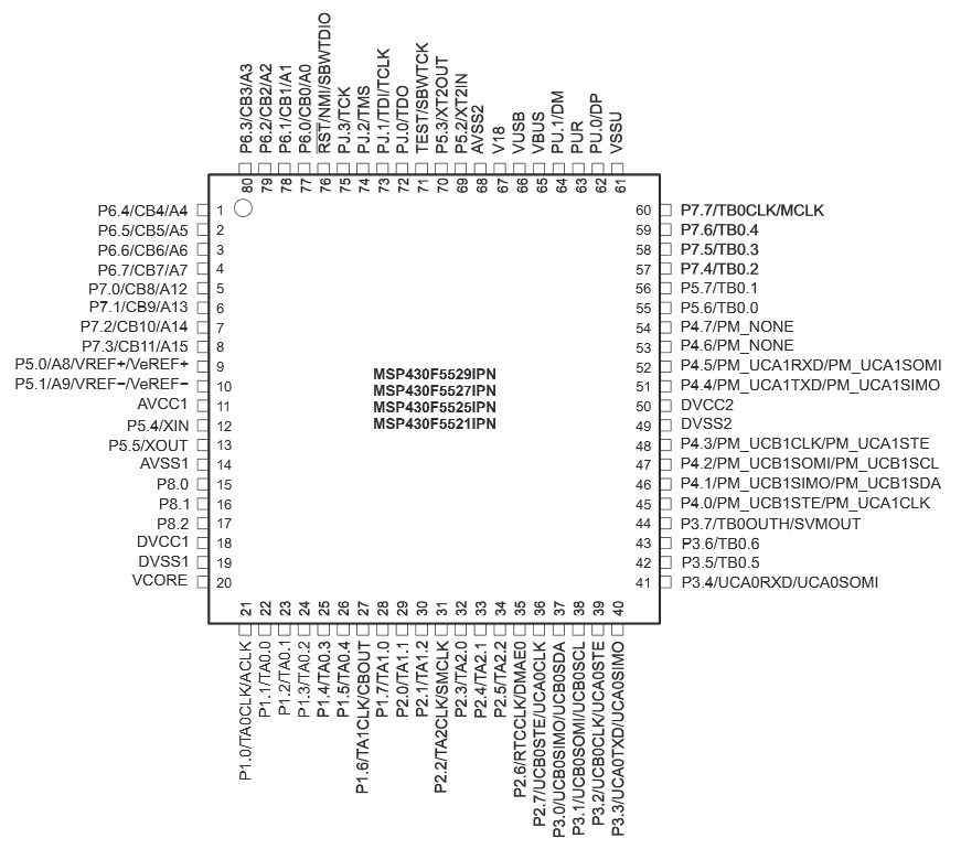
i finally implemented  sd card operation for msp430f5529. i wanna change 5529 sd card code to msp430fg439 but i have below problem and i need your helps;

***msp430f5529 usci spi was used to communicate sd card but unfortunately msp430fg439 has usart spi. i changed my code according to usart spi but it didn't work. can i change usci spi to usart spi, does it creates any problem?

  • Hi!

    USART means, the interface can be synchronous or asynchronous. UART would be asynchronous, it has no clock signal. I²C and SPI are synchronous. Your USART is capable of handling both, not at the same time, of course. If you configure the USART for SPI configuration you can use it the same way as before. The code won't be exactly the same since the register names might be different. So you have to change some things in the configuration code, but these are only a few lines. And the names for the receive and transmit buffer might be different, too.

    The user's guide

    in chapter 18 describes the use of the USART in SPI mode. At the end of that chapter you can find the registers for configuration.

    Dennis

  • i changed spi codes like this but it didn't work and i don't know why, always my code stuck at communication part.  here my spi codes;

    msp430f5529 spi part

    /***************************************************************************//**
     * @file       HAL_SDCard.c
     * @addtogroup HAL_SDCard
     * @{
     ******************************************************************************/
    #include "msp430.h"
    #include "HAL_SDCard.h"
    
    // Pins from MSP430 connected to the SD Card
    #define SPI_SIMO        BIT0  // 0x0001
    #define SPI_SOMI        BIT1  // 0x0002
    #define SPI_CLK         BIT2  // 0x0004
    #define SD_CS           BIT5  // 0x0020
    
    // Ports
    #define SPI_SEL         P3SEL
    #define SPI_DIR         P3DIR
    #define SPI_OUT         P3OUT
    #define SPI_REN         P3REN
    #define SD_CS_SEL       P3SEL
    #define SD_CS_OUT       P3OUT
    #define SD_CS_DIR       P3DIR
    
    /***************************************************************************//**
     * @brief   Initialize SD Card
     * @param   None
     * @return  None
     ******************************************************************************/
    
    void SDCard_init(void)
    {
    	//*
        // Port initialization for SD Card operation
        SPI_SEL |= SPI_CLK + SPI_SOMI + SPI_SIMO;			   //Set P3.0-2 to peripherals
        SPI_DIR |= SPI_CLK + SPI_SIMO;						   //THIS MIGHT BE UNNECESSARY****
        SPI_REN |= SPI_SOMI;                                   // Pull-Ups on SD Card SOMI
        SPI_OUT |= SPI_SOMI;                                   // Certain SD Card Brands need pull-ups
    
        SD_CS_SEL &= ~SD_CS;
        SD_CS_OUT |= SD_CS;
        SD_CS_DIR |= SD_CS;
    
        // Initialize USCI_B1 for SPI Master operation
        UCB0CTL1 |= UCSWRST;                                   // Put state machine in reset
        UCB0CTL0 = UCCKPL + UCMSB + UCMST + UCMODE_0 + UCSYNC; // 3-pin, 8-bit SPI master
        // Clock polarity select - The inactive state is high
        // MSB first
        UCB0CTL1 = UCSWRST + UCSSEL_2;                         // Use SMCLK, keep RESET
        UCB0BR0 = 63;                                          // Initial SPI clock must be <400kHz
        UCB0BR1 = 0;                                           // f_UCxCLK = 25MHz/63 = 397kHz
        UCB0CTL1 &= ~UCSWRST;                                  // Release USCI state machine
        UCB0IFG &= ~UCRXIFG;
    }
    
    /***************************************************************************//**
     * @brief   Enable fast SD Card SPI transfers. This function is typically
     *          called after the initial SD Card setup is done to maximize
     *          transfer speed.
     * @param   None
     * @return  None
     ******************************************************************************/
    
    void SDCard_fastMode(void)
    {
        UCB0CTL1 |= UCSWRST;                                   // Put state machine in reset
        UCB0BR0 = 2;                                           // f_UCxCLK = 25MHz/2 = 12.5MHz
        UCB0BR1 = 0;
        UCB0CTL1 &= ~UCSWRST;                                  // Release USCI state machine
    }
    
    /***************************************************************************//**
     * @brief   Read a frame of bytes via SPI
     * @param   pBuffer Place to store the received bytes
     * @param   size Indicator of how many bytes to receive
     * @return  None
     ******************************************************************************/
    
    void SDCard_readFrame(uint8_t *pBuffer, uint16_t size)
    {
        uint16_t gie = __get_SR_register() & GIE;              // Store current GIE state
    
        __disable_interrupt();                                 // Make this operation atomic
    
        UCB0IFG &= ~UCRXIFG;                                   // Ensure RXIFG is clear
    
        // Clock the actual data transfer and receive the bytes
        while (size--){
            while (!(UCB0IFG & UCTXIFG)) ;                     // Wait while not ready for TX
            UCB0TXBUF = 0xff;                                  // Write dummy byte
            while (!(UCB0IFG & UCRXIFG)) ;                     // Wait for RX buffer (full)
            *pBuffer++ = UCB0RXBUF;
        }
    
        __bis_SR_register(gie);                                // Restore original GIE state
    }
    
    /***************************************************************************//**
     * @brief   Send a frame of bytes via SPI
     * @param   pBuffer Place that holds the bytes to send
     * @param   size Indicator of how many bytes to send
     * @return  None
     ******************************************************************************/
    
    void SDCard_sendFrame(uint8_t *pBuffer, uint16_t size)
    {
        uint16_t gie = __get_SR_register() & GIE;              // Store current GIE state
    
        __disable_interrupt();                                 // Make this operation atomic
    
        // Clock the actual data transfer and send the bytes. Note that we
        // intentionally not read out the receive buffer during frame transmission
        // in order to optimize transfer speed, however we need to take care of the
        // resulting overrun condition.
        while (size--){
            while (!(UCB0IFG & UCTXIFG)) ;                     // Wait while not ready for TX
            UCB0TXBUF = *pBuffer++;                            // Write byte
        }
        while (UCB0STAT & UCBUSY) ;                            // Wait for all TX/RX to finish
    
        UCB0RXBUF;                                             // Dummy read to empty RX buffer
                                                               // and clear any overrun conditions
    
        __bis_SR_register(gie);                                // Restore original GIE state
    }
    
    /***************************************************************************//**
     * @brief   Set the SD Card's chip-select signal to high
     * @param   None
     * @return  None
     ******************************************************************************/
    
    void SDCard_setCSHigh(void)
    {
        SD_CS_OUT |= SD_CS;
    }
    
    /***************************************************************************//**
     * @brief   Set the SD Card's chip-select signal to low
     * @param   None
     * @return  None
     ******************************************************************************/
    
    void SDCard_setCSLow(void)
    {
        SD_CS_OUT &= ~SD_CS;
    }
    
    /***************************************************************************//**
     * @}
     ******************************************************************************/
    

    msp430fg439 spi part

    /***************************************************************************//**
     * @file       HAL_SDCard.c
     * @addtogroup HAL_SDCard
     * @{
     ******************************************************************************/
    #include "msp430.h"
    #include "HAL_SDCard.h"
    
    // Pins from MSP430 connected to the SD Card
    #define SPI_SIMO        BIT1 // 0x0001
    #define SPI_SOMI        BIT2  // 0x0002
    #define SPI_CLK         BIT3  // 0x0004
    #define SD_CS           BIT0  // 0x0020
    
    // Ports
    #define SPI_SEL         P3SEL
    #define SPI_DIR         P3DIR
    #define SPI_OUT         P3OUT
    #define SD_CS_SEL       P3SEL
    #define SD_CS_OUT       P3OUT
    #define SD_CS_DIR       P3DIR
    
    /***************************************************************************//**
     * @brief   Initialize SD Card
     * @param   None
     * @return  None
     ******************************************************************************/
    
    void SDCard_init(void)
    {
    	//*
        // Port initialization for SD Card operation
        SPI_SEL |= SPI_CLK + SPI_SOMI + SPI_SIMO;			   //Set P3.0-2 to peripherals
        SPI_DIR |= SPI_CLK + SPI_SIMO;						   //THIS MIGHT BE UNNECESSARY****
        SPI_OUT |= SPI_SOMI;                                   // Certain SD Card Brands need pull-ups
    
        SD_CS_SEL &= ~SD_CS;
        SD_CS_OUT |= SD_CS;
        SD_CS_DIR |= SD_CS;
    
    
        UCTL0  |= SWRST;
        ME1    |= USPIE0;                            // Enable USART0 SPI mode
        UCTL0  |= CHAR + SYNC + MM ;                // 8-bit SPI Master **SWRST**
        UTCTL0 |= CKPL + SSEL1 + SSEL0 + STC;     // SMCLK, 3-pin mode
    
        UCTL0 = SWRST;
    
    
        U0BR0 = 63;                                          // Initial SPI clock must be <400kHz
        U0BR1 = 0;                                           // f_UCxCLK = 6MHz/16 = 377kHz
    
        UCTL0 &= ~SWRST;                                  // Release USCI state machine
        IFG1  &= ~URXIFG0;
    
    }


    /***************************************************************************//**
     * @brief   Enable fast SD Card SPI transfers. This function is typically
     *          called after the initial SD Card setup is done to maximize
     *          transfer speed.
     * @param   None
     * @return  None
     ******************************************************************************/
    
    void SDCard_fastMode(void)
    {
    	UCTL0  |= SWRST;                               // Put state machine in reset
    	U0BR0 = 2;                                           // f_UCxCLK = 6MHz/2 = 3MHz
    	U0BR1 = 0;
    	UCTL0 &= ~SWRST;                                  // Release USCI state machine
    }
    
    /***************************************************************************//**
     * @brief   Read a frame of bytes via SPI
     * @param   pBuffer Place to store the received bytes
     * @param   size Indicator of how many bytes to receive
     * @return  None
     ******************************************************************************/
    
    void SDCard_readFrame(uint8_t *pBuffer, uint16_t size)
    {
        uint16_t gie = __get_SR_register() & GIE;              // Store current GIE state
    
        __disable_interrupt();                                 // Make this operation atomic
    
        IFG1 &= ~URXIFG0;                                   // Ensure RXIFG is clear
    
        // Clock the actual data transfer and receive the bytes
        while (size--){
           while (!(IFG1 & UTXIFG0)) ;                     // Wait while not ready for TX
            U0TXBUF = 0xff;                                  // Write dummy byte
            while (!(IFG1 & URXIFG0)) ;                     // Wait for RX buffer (full)
            *pBuffer++ = U0RXBUF;
        }
    
        __bis_SR_register(gie);                                // Restore original GIE state
    }
    
    /***************************************************************************//**
     * @brief   Send a frame of bytes via SPI
     * @param   pBuffer Place that holds the bytes to send
     * @param   size Indicator of how many bytes to send
     * @return  None
     ******************************************************************************/
    
    void SDCard_sendFrame(uint8_t *pBuffer, uint16_t size)
    {
        uint16_t gie = __get_SR_register() & GIE;              // Store current GIE state
    
        __disable_interrupt();                                 // Make this operation atomic
    
        // Clock the actual data transfer and send the bytes. Note that we
        // intentionally not read out the receive buffer during frame transmission
        // in order to optimize transfer speed, however we need to take care of the
        // resulting overrun condition.
        while (size--){
           while (!(IFG1 & UTXIFG0)) ;                     // Wait while not ready for TX
            U0TXBUF = *pBuffer++;                            // Write byte
        }
       while ((!(IFG1 & URXIFG0)) & (!(IFG1 & UTXIFG0))) ;                            // Wait for all TX/RX to finish
    
        	U0RXBUF;                                             // Dummy read to empty RX buffer
                                                               // and clear any overrun conditions
    
        __bis_SR_register(gie);                                // Restore original GIE state
    }
    
    /***************************************************************************//**
     * @brief   Set the SD Card's chip-select signal to high
     * @param   None
     * @return  None
     ******************************************************************************/
    
    void SDCard_setCSHigh(void)
    {
        SD_CS_OUT |= SD_CS;
    }
    
    /***************************************************************************//**
     * @brief   Set the SD Card's chip-select signal to low
     * @param   None
     * @return  None
     ******************************************************************************/
    
    void SDCard_setCSLow(void)
    {
        SD_CS_OUT &= ~SD_CS;
    }
    
    /***************************************************************************//**
     * @}
     ******************************************************************************/

  • I haven't looked through your complete code now, but what is obvious:

    Definitions for the MSP430F5529:

    #define SPI_SIMO        BIT0  // 0x0001
    #define SPI_SOMI        BIT1  // 0x0002
    #define SPI_CLK         BIT2  // 0x0004
    #define SD_CS           BIT5  // 0x0020

    And the definitions for the MSP430FG439:

    #define SPI_SIMO        BIT0  // 0x0001
    #define SPI_SOMI        BIT1  // 0x0002
    #define SPI_CLK         BIT2  // 0x0004
    #define SD_CS           BIT5  // 0x0020

    They are the same!

    Now compare the pinouts. The MSP430F5529:

    This has SPI SIMO at P3.0, SPI SOMI at P3.1 and SPI CLOCK at P3.2 (as defined in your code, of course).

    Now let's look at your new MSP430FG439:

    This has SPI SIMO at P3.1, SPI SOMI at P3.2 and SPI CLOCK at P3.3 - so how should this work if you do not adapt the connections according to your new processor?

    Just copy paste is not possible. As I said, the configuration has to be changed.

    Dennis

  • definitions for the MSP430FG439

    #define SPI_SIMO BIT1 // 0x0001
    #define SPI_SOMI BIT2 // 0x0002
    #define SPI_CLK BIT3 // 0x0004
    #define SD_CS BIT0 // 0x0020
  • I don't know your hardware connection, so I don't know where chip select is connected to.

    And I don't know if the PxSEL settings are the same for both processors. You will find them in the datasheet.

    Dennis

  • "#define SPI_SIMO BIT1 // 0x0001"
    That's not enough. The port itself has changed too (which isn't covered by the bit defines at all).

    Also, minimum divider for the baudrate is /2, while the USCI can do /1 if running as master. But that's correct in the code.
    The USART also offers the TXEPT flag, which can be used to determine whether sending is complete (must be set before you can de-assert CS). The USCI has the UCBUSY bit that serves mainly the same purpose but must be clear to indicate the end of the transfer.
  • Hi User430679. 

    I am having a lot of trobles to make the the implementation for sd card operations for msp430f5529. I tried to port the code of the experiment board to my launch pad but I have completed three monthes with no success. Is it possible for you to share your code and modifications in the library for me ? I'd appreciate very much because I am stuck in this part of my project. 

    Thank you so much,

    William Macedo

  • At which point does your code fail? Does it do the initialization of the card? If not: what does the card return for your init attempts?
    Which kind of card are you using? Note that micro-SD cards require using ACMD41 while standard SD cards can be initialized with the same CMD1 that MMC cards use. Also, SDHC and SDXC cars require a different command sequence than the original SD cards. IIRC you need to read the register for supply voltage before you can go idle state (CMD0).
    Probably the code you're trying to port was never written to be used with the cards you have.
    BTW: be sure your clock speed is okay (check your clock system setup). During init, only 400kHz SPI clock are allowed.
  • Hi Jens !

    The code fails just in the initialization. I am using the FatFs library and the code returns "FR_NOT_READY" what means a failure in the disk_initialization function. I am using a micro-SD card with FAT32, maybe here is the problem as you said. How can I change for ACMD41 command ?

    I checked the Clock Signal in the Osciloscope and it seems to be fine. I am using 397kHz.
  • I use a state machine to initialize my SD card (running in a 1ms interrupt). I'll try to reproduce it here

    1) after card insert detected: wait 100ms, then ->2
    2) set clock to 400kHz (max), send 10 times 0xff with CS=high (card NOT selected), then ->3
    3) select card, send CMD0, (GO_IDLE_STATE) then ->4
    4) wait for response. If response != 0x01 ->2 else release card, send 1*0xff, then ->5
    5) select card, send CMD55(APP_CMD), ->6
    6) wait for response. release card, send 1*0xff. If response !=0 and != 1, then it is an MMC card, ->7, else ->11 (SD card)
    7) select card, send CMD0 (GO_IDLE_STATE), then ->8
    8) wait for response. release card, send 1*0xff, then ->9
    9) select card, send CMD1 (SEND_OP_COND), ->10
    10) wait for response. release card, send 1*0xff. If response is 0x01, then ->13 else ->9
    11) select card, send ACMD41 (SD_APP_OP_COND), ->12
    12) wait for response, release card, send 1*0xff. if response is...
    0: -> 13 (proceed)
    1: ->5 (card still initializing)
    4: ->7 (probably an MMC+ card, treat like MMC card)
    anything else: reject card
    13) select card, send CMD9 (READ_CSD), ->14
    14) wait for response. If response !=0: reject card. If response is 0 ->15
    15) wait for 0xfe (START_DATA_BLOCK_TOKEN), then ->16
    16) receive 16 bytes CSD, then send 2*0xff, then release card, send 1*0xff ->
    17) wait 256ms, ->18
    18) card initialized. Wait for card removed, then return to ->1

    I hope I didn't miss a step. The 'empty' transfers after releasing the card have proven to be necessary. Apparently, the cards use the SPI clock (even if not selected) for advancing their internal state machine or whatsoever. So the interface is not strictly SPI.

    After you reached 18), the card can be accessed with (usually) up to 25MHz clock speed. You also have the CSD, so you know the capacity and other informations.
    The CSD also tells you whether the card supports 512 byte sectors for write (mandatory for using FAT). Cards with 2GB or 4GB size may only support 1k writes. This sector limit exists even though the read and write commands take a 32 bit linear byte address that may be not a sector boundary. But using this will not work as one might think. Better keep one write = one sector.
    On SDHC cards, the CSD has a different format. Also, the read and write commands take a 32 bit sector address (expanding the address range to 4G*512 bytes). They usually support 512byte sectors.
    IIRC, SDXC cards require reading another register (supply voltage range register) after or before reading the CSD.
    However, I never used SDHC or SDXC cards. 1GB was always enough for me for data logging. Maybe I'll have to update my code since 1GB cards are not that easy to find anymore.
  • Thank you Jens! I solved the problem.
  • How? Did you use my pseudo-code or did you find and fix a bug in your own implementation?
    Others might want to know when reading this thread.

**Attention** This is a public forum