This thread has been locked.

If you have a related question, please click the "Ask a related question" button in the top right corner. The newly created question will be automatically linked to this question.

USCI_B0 I2C MSP430F5529

Other Parts Discussed in Thread: MSP430F5529

Hello,

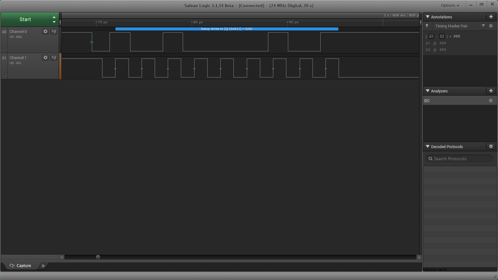
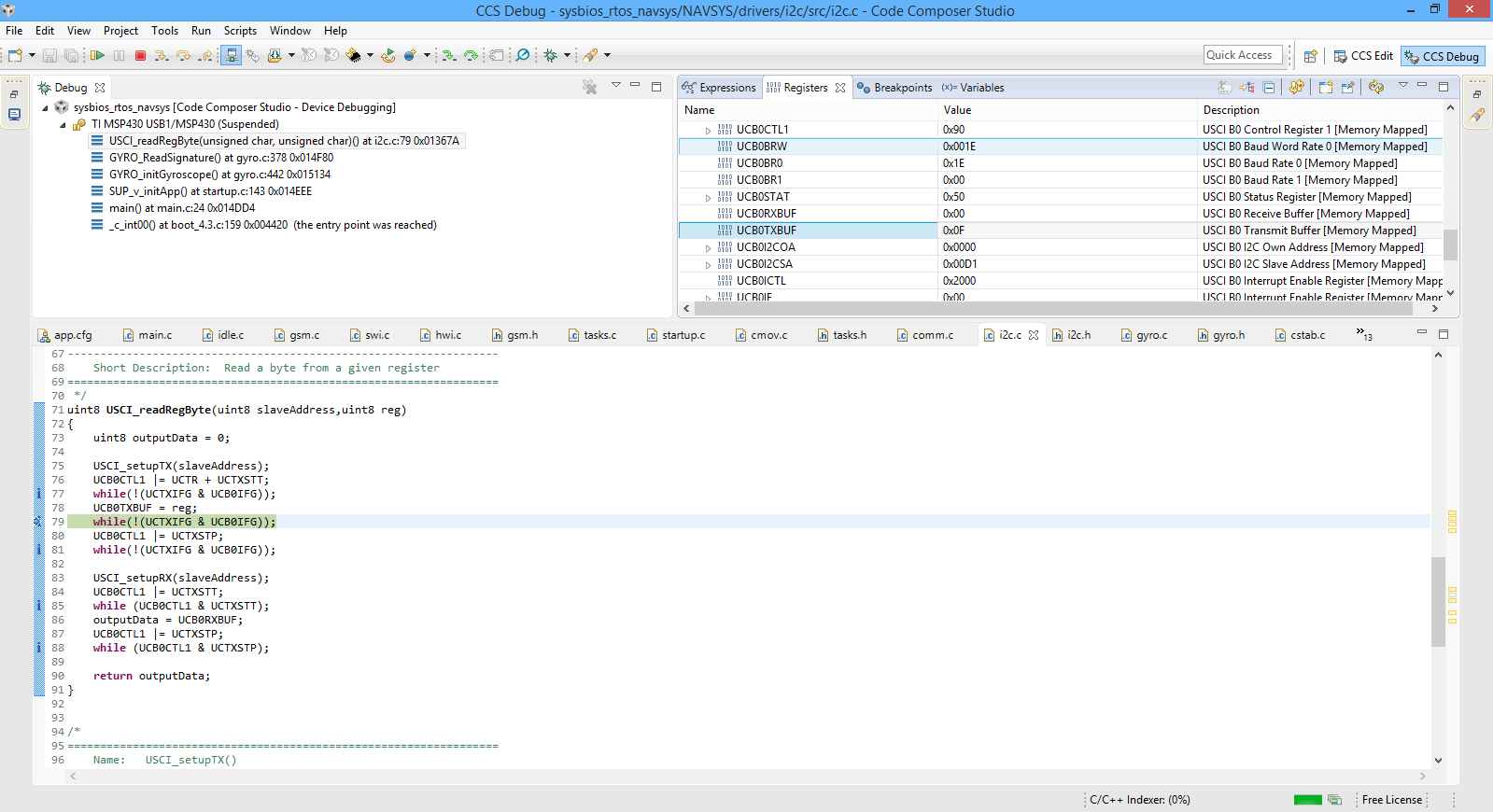
I'm going to read some data from a gyroscope connected to the MSP430F5529 microcontroller through the I2C connection.I also use the driverlib from the Ti version 2_10_00_09. The problem comes when I try to get a value from the sensor, it stays blocked at the following line.

..........
   // Poll for transmit interrupt flag.
    while(!(HWREG8(baseAddress + OFS_UCBxIFG) & UCTXIFG))
    {
        ;
    }
.........

Could someone explain me why  happens this ?

  • Hello,

    UCTXIFG is the transmit interrupt flag stored inside of the UCBxIFG register and is set when UCBxTXBUF is empty, meaning that UCBxTXBUF is ready for new data. UCTXIFG is automatically reset if a character is written to UCBxTXBUF or if a NACK is received. The code above will therefore stay in the while loop until UCTXIFG is equal to 1, where the UCBxTXBUF is empty and ready for new data. This while loop is typically used as a test performed before writing more data to UCBxTXBUF.

    Regards,
    Ryan
  • Hello,

    Thank you for your answer and sorry for my late. 

    Yes, that's right, but why gets stuck there? It means that value is not shifted ? If yes, what would be the reason ?

    Thank you,

  • Typically for I2C it could mean that the lines are not pulled up effectively. Make sure that pullup resistors are keeping the lines high when inactive.

    Ryan
  • You made sure to put the port pins into peripheral mode and didn't leave them in GPIO mode? That's an easy thing to forget and could explain your problem.

    GPIO_setAsPeripheralModuleFunctionInputPin( GPIO_PORT_P3, (GPIO_PIN0|GPIO_PIN1) );
  • The lines are linked there as you can see in the picture :

  • Yes Brian, I did it : P3SEL |= BIT0 | BIT1;
  • Are you sure that 10K is "stiff" enough? You need to look at what the pin capacitance is on each line (devices and the MSP430) and see what the rise time of the signal would be (remember, I2C is open-drain). If the connections are completely on a circuit board then generally you can ignore trace capacitance. You want the signal to be able to rise at least 10 times faster than clock rate.

    You can look at the signal quality with a scope. Alternately you can slow the I2C clock rate down and see if it starts working. If it does, try decreasing the resistor values.
  • Hello,

    I think it is not a HW problem, because these values are taken  from the device datasheet. By the way, I try to connect the A3G4250D gyroscope module. Should be a problem the address of the slave ? I mean,the slave address for this device is a little bit confusing..

    Thank you,

  • Based on the A3G4250D datasheet I would make sure that the CS pin is high to enable I2C operation. As Brian suggested it would be good to use an oscilloscope to ensure that the I2C lines are operating as intended.

    The slave address is 6 standard bits (110100) + SDO pin state + read/write command. From the datasheet:
    "If the SDO pin is connected to the voltage supply, LSb is ‘1’ (address 1101001b). Otherwise, when the SDO pin is connected to ground, the LSb value is ‘0’ (address 1101000b). This solution permits the connection and addressing of two different gyroscopes to the same I2C bus."

    So reflect the state of your SDO pin, most likely grounded and therefore 0. Then if you want to write to the A3G4250D the LSB of the slave address is 0, but for a read it is 1. Your slave address is therefore 11010001 (D1h) for a read and 11010000 (D0h) for a write. Please follow the tables in Section 5.1.1 for proper communication protocol with the gyroscope.

    Regards,
    Ryan
  • This is what I've got with a logic analyzer: 

  • When I paused the program, it gets stuck at that while. Therefore the value from UCB0TXBUF is not sent.

  • Are you sure that you are receiving the slave acknowledge necessary to clear the UCTXIFG? Your logic analyzer screen shot is a bit confusing, can you confirm that the correct slave address is being sent? Otherwise you will not receive a slave acknowledge.

    Ryan
  • I am not sure the slave address is sent, this is the only thing I can see with the logic analyzer. I've also checked the CS pin ans is linked to 3V3.
  • The blue text says "Setup Write to [Q(0x51)] + NAK", if Q is the slave address then you're not sending the correct address. Once again, it's hard to tell from that screenshot but at any rate I doubt you are receiving the NACK needed to clear UCTXIFG.

  • I am at a loss what to say, but I think I found the issue. I've measured the voltage for the device and I've seen that the voltage is 3.88V. It means just a thing, the LDO is broken. I will try to replace it and I will post again.

    Thank you for your time,
    Have a nice evening,
  • "if Q is the slave address "
    Yes, the analyzer tells that slave 0x51 is addressed for write operation (start byte 0xa2 is sent) but the slave doesn't answer.
    The screenshot leaves no doubt.

    If 0x51 is the 7 bit address of the slave (so 0xa2 and 0xa3 are used as start byte to addressed it), then there is a hardware problem. Did you connect the common GND? (don't laugh - happened quite often in this forum)

    If the slave doesn't answer, the USCI is waiting for you to notice that UCNACKIFG is set and you set UCTXSTP to end the communication. UCTXIFG is cleared at the NACK.

    The broken LDO is of course a problem, but shouldn't break the communication - unless the MSP has been fried.

**Attention** This is a public forum