


Other Parts Discussed in Thread: MSP430G2553
Hi, I am using msp430g2553 with launchpad, editing with CCS. My problem is Baudrate. In the userguide:
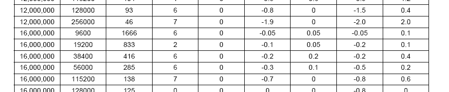
it says UCBRx should be 1666 with UCBRSx 6 set for baudrate 9600. So it tells me that I should set
UCA0BR0 = 0x82;
UCA0BR1 = 0x06;
UCA0MCTL = UCBRS_6;
however, when I do that, and oscillate with TXBUF= OxFF it oscillate at 953 Hz. (FF + 1 bit stop bit makes an oscillation at byte level) So baudrate is like 953x8=7624Hz. NOT 9600 Hz. So I can not communicate with Putty on my computer on 9600 Baudrate. However, I can communicate with my PC with uart using this code below:
#include <msp430g2553.h>
#include <string.h>
#include <stdio.h>
/*
 * main.c
 */

void uart_conf(void);
void clck_conf(void);
char byte_to_crc[20];
unsigned short crc;
unsigned int len;
unsigned int pos;
unsigned int i;
unsigned int request_indicator=0;
char received_frame[20];
char transmitted_frame[20];
unsigned int byte_count_to_receive;
unsigned int byte_count_to_transmit;
unsigned int received_byte_counter;
unsigned int transmitted_byte_counter;

char reg_add_hi;
char reg_add_lo;
char nop_hi;
char nop_lo;
char crc_hi;
char crc_lo;

unsigned short mod_rtu_crc(char*, int);    // generate crc
void read_holding_regs(char, char , unsigned short , unsigned short);   // reading holding regs function

void main(void) {
    WDTCTL = WDTPW | WDTHOLD;	// Stop watchdog timer
    clck_conf();
    uart_conf();
    read_holding_regs(0x00, 0x03, 0x0001, 0x0002);
	//IFG2 &= ~UCA0RXIFG;
	UC0IE |= UCA0TXIE | UCA0RXIE;
	__bis_SR_register(CPUOFF + GIE); // Enter LPM0 w/ int until Byte RXed

	while(1);


}


void uart_conf(void){

	UCA0CTL1 |= UCSWRST;         //Reset USCI
	UCA0CTL0 &= ~UCSYNC;  // Clear UCSYNC for UART communication;
	P1SEL |= (BIT1 | BIT2);       // Select for spec. function directions UART TX and RX
	P1SEL2 |= (BIT1 | BIT2);
	UCA0CTL1 |= UCSSEL_2;       // BTCL = SMCLK
	UCA0BR0 = 0xFF;
	UCA0BR1 = 0x05;                       // F_16MHZ / 1666 ~= 9600 KHz  0x0682 = 1666
	UCA0MCTL = UCBRS_6;    // Set modulation for minimum error rate (see spec...) 9600 Kps UCBRSx = 6 UcBRFx = 0;
	UCA0CTL1 &= ~UCSWRST;          // Un Reset USCI
	//UC0IE |= (UCA0RXIE | UCA0TXIE);     // enable interrupts


}

void clck_conf(void){

	BCSCTL1 = CALBC1_16MHZ; // Set DCO 16 MHz
	DCOCTL = CALDCO_16MHZ;

}

void read_holding_regs(char slave_add, char function, unsigned short reg_add, unsigned short nop){
	byte_to_crc[0] = slave_add;
	byte_to_crc[1] = function;
	reg_add_hi = reg_add >> 8;
	reg_add_lo = reg_add & 0x00ff;
	byte_to_crc[2] = reg_add_hi;
	byte_to_crc[3] = reg_add_lo;
	nop_hi = nop >> 8;
	nop_lo = nop & 0x00ff;
	byte_to_crc[4] = nop_hi;
	byte_to_crc[5] = nop_lo;

	len = 6;

	mod_rtu_crc(byte_to_crc, len);
	crc_hi = crc >> 8;
	crc_lo = crc & 0x00ff;

	transmitted_frame[0] = byte_to_crc[0];
	transmitted_frame[1] = byte_to_crc[1];
	transmitted_frame[2] = byte_to_crc[2];
	transmitted_frame[3] = byte_to_crc[3];
	transmitted_frame[4] = byte_to_crc[4];
	transmitted_frame[5] = byte_to_crc[5];
	transmitted_frame[6] = crc_lo;
	transmitted_frame[7] = crc_hi;

	received_byte_counter = 0;
	byte_count_to_receive = len + (int)nop + 2;    // + 2 for CRC and + No of Points because 2x nop comes back as response
	byte_count_to_transmit = len + 2;
	// start serial transmit
	__delay_cycles(64000);   //  Wait for 4 ms


}

// Compute the MODBUS RTU CRC
unsigned short mod_rtu_crc(char* bytes, int len)
{
	crc = 0xFFFF;

  for(pos = 0; pos < len; pos++){
    crc ^= (unsigned short)bytes[pos];          // XOR byte into least sig. byte of crc

    for(i = 8; i != 0; i--){    // Loop over each bit
      if((crc & 0x0001) != 0){      // If the LSB is set
        crc >>= 1;                    // Shift right and XOR 0xA001
        crc ^= 0xA001;
      }
      else{                            // Else LSB is not set
        crc >>= 1;                    // Just shift right
      }
    }
  // Note, this number has low and high bytes swapped, so use it accordingly (or swap bytes)

}
return crc;
}

#pragma vector=USCIAB0RX_VECTOR
__interrupt void USCI0RX_ISR(void)
{

	if(received_byte_counter != byte_count_to_receive-1){        //if receive is not over
		received_byte_counter++;
		received_frame[received_byte_counter]= UCA0RXBUF;
	}
	else{
		received_frame[received_byte_counter]= UCA0RXBUF;
		UC0IE &= ~UCA0RXIE;     // disable RX interrupts
	}

}


#pragma vector=USCIAB0TX_VECTOR
__interrupt void USCI0TX_ISR(void)
{
	if(transmitted_byte_counter != byte_count_to_transmit-1){        //if transmit is not over
		transmitted_byte_counter++;
		UCA0TXBUF = transmitted_frame[transmitted_byte_counter];
	}
	else{
		UCA0TXBUF = transmitted_frame[transmitted_byte_counter];
		UC0IE &= ~UCA0TXIE;     // disable RX interrupts
		//__delay_cycles(64000);   //  Wait for 4 ms
	}
}
AS you see, I changed the values to
	UCA0BR0 = 0xFF;
	UCA0BR1 = 0x05;

And I surprisingly can communicate?! Why is that, did I read the user guide wrong? I am open to any sggestion. Thanks.


