This thread has been locked.

If you have a related question, please click the "Ask a related question" button in the top right corner. The newly created question will be automatically linked to this question.

MSP430 SPI slave MODE0 issue - bit shifting

Other Parts Discussed in Thread: MSP430F5529, MSP430F435

I have configured MSP430F5529 Experimenter Board as SPI slave in MODE0 configuration.

So my program is , whenever I receive a byte from master a constant value 0xAA is put into TX buffer of slave which will be shifted out in the next transaction. I can see that the SPI master always get 0x55 (which is 1 bit shifted of 0xAA). I probed the SPI lines to get an idea on what's going on.

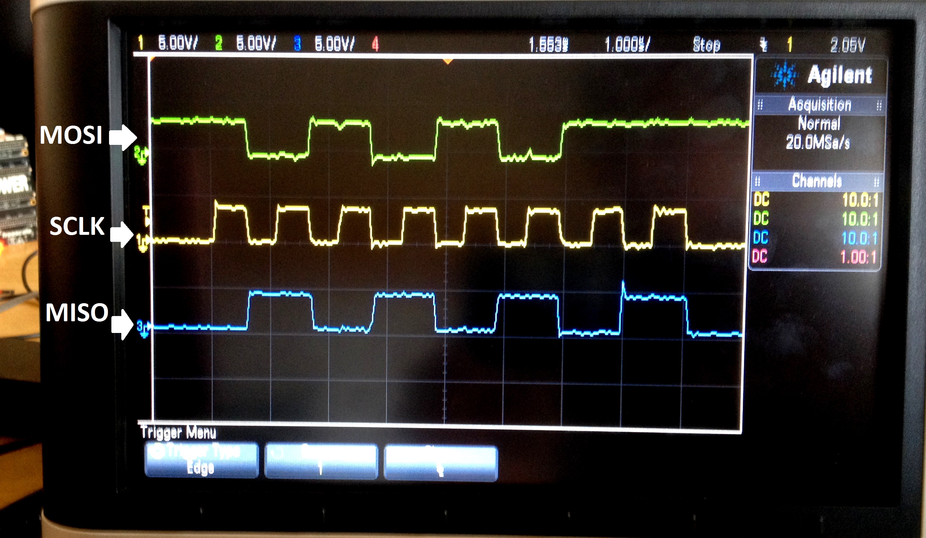
So here , in SPI MODE0 , data sampling -> rising edge, data toggling -> falling edge

the slave is receiving the data from master properly, but transmission of 0xAA from slave is shown MISO (blue waveform).

Explanation:

*. Since the toggling edge is falling , slave skips the first rising edge and the data from slave is made available only on the first falling edge,

*. By that time master sampled the first bit in the first clock itself which is read as 0.

*. This is why I'm missing the first bit, or the Byte gets shifted by 1 bit.

Does MSP430 has some kind of limitation in MODE0 ?

Hers's my code

int main(void)
{
    WDTCTL = WDTPW+WDTHOLD;                   // Stop watchdog timer
    Clock_Init();

    P4SEL |= BIT0 + BIT4 + BIT5;                            // P4.5,4,,0 option select

    UCA1CTL1 |= UCSWRST;                      // **Put state machine in reset**
    UCA1CTL0 |= UCSYNC+UCMSB+UCCKPH;
    UCA1CTL1 &= ~UCSWRST;                     // **Initialize USCI state machine**
    UCA1IE |= UCRXIE;                         // Enable USCI_A0 RX interrupt

    __enable_interrupt();        // enable interrupts
    while(1);
}

#pragma vector=USCI_A1_VECTOR
__interrupt void USCI_A1_ISR(void)

{
    switch(__even_in_range(UCA1IV,4))
    {
    case 0:break;                             // Vector 0 - no interrupt
    case 2:                                   // Vector 2 - RXIFG
        raw_buff = UCA1RXBUF;
        while (!(UCA1IFG&UCTXIFG));
        UCA1TXBUF = 0xaa;
        break;
    case 4:break;                             // Vector 4 - TXIFG
    default: break;
    }
}

  • Hi,

    I think you are actually running into erratum USCI40.  If you take a look at the F5529 Erratasheet, you can see the errata descriptions.  The workaround is to repopulate UCAxTXBUF before the next transmission.  I see that your code shows that the TXBUF is reloaded, but you may want to check the timing on that to make sure it actually occurs after the previous transaction completes and before the next one starts.  This timing can be tricky when the 430 is configured as the SPI slave.

    Mike

  • Hi,

    Thanks for the reply,,

    Actually we solved the problem using SPI slave in 4 pin mode,

    When using 4 pin mode , in SPI mode0 the slave pushes the first bit on to the MISO line on STE assertion from master, which was not happening in 3 pin mode so that the slave will detect only on the falling edge on first clock.
  • It's also possible that you picked the wrong operation mode. You set UCPH, which is (in a narrow time window) compatible to the opposite mode, with UCPL set and UCPH clear. Note that TI notation differs form Motorola notation regarding SPI modes. SO check the actual meaning of the mode, not its name.

    Clemens: USCI40 description isn't very clear and the workaround is fuzzy too. I agree that limiting the write to TXBUF only after the last bit of the last byte has been sent and before the master requests the next bit, is a bit tricky. More than a bit. It makes the slave mode useless for higher SPI clock speeds and also prevents use of the TX interrupt. If this is what the workaround means. In this case, I'd call this erratum a real showstopper.
  • Hi Jens,

    Thanks for the reply,

    But could you please clarify me why it was failing to change the data on the first rising edge of the clock (in 3 pin spi mode), and it change the data on the MISO line on the second rising edge only..

    I'm curious to know what really happened?
  • Here's some more information about erratum USCI40:

    e2e.ti.com/.../1418647
  • I assume you used 4-wire mode and forgot about 3-wire mode? I currently have the same issue and I can't use 4-wire mode. I'm loading TXBUF before every transmission, but it looks like the buffer isn't loaded into the shift register until the first clock.
  • I'll post this here as lack of better place. I seem to have stumbled on how to make SPI Slave with CKPH Set work on the MSP430F5529 in 3-wire mode for me.

    There are several other posts about this issue -
    e2e.ti.com/.../423468
    e2e.ti.com/.../363755
    e2e.ti.com/.../


    A little background -
    Basically, I'm working with a system where I have to be the SPI Slave, CKPH Set, CKPL Reset. I have a MSP430F5529 EXP board that is taking the place of an MSP430F435/F436 for this project. Everything has been working great on the F435 for years, and we cannot change the setup on the SPI master. I also have a pause between each byte.

    I had the F5529 setting the TXBUF before enabling the RX Interrupt like I think most people do (and like the example). Here I was always a clock behind.

    //setup the CTL0 and CTL1 registers before this...
    -> UCB0TXBUF = SPI_TX_MSG[Index]; //Load TX Buffer
    UCB0CTL1 &= ~UCSWRST; // **Initialize USCI state machine**
    UCB0IE |= UCRXIE; // Enable USCI_B0 RX interrupt

    By moving where I load TXBUF, I found that the SOMI line was immediately toggled to the necessary value for the first bit. Like this:

    UCB0CTL1 &= ~UCSWRST; // **Initialize USCI state machine**
    UCB0IE |= UCRXIE; // Enable USCI_B0 RX interrupt
    -> UCB0TXBUF = SPI_TX_MSG[Index]; // This triggers SOMI to change before first clock.


    On the interrupt, all I do is load the next byte into the buffer after saving off the receive buffer. Nothing funny there.
    UCB0TXBUF = SPI_TX_MSG[Index];


    As I said, this seems to work for me. I have some time between byte transmissions to reload the buffer and let the system catch up. Good luck!

**Attention** This is a public forum