This thread has been locked.

If you have a related question, please click the "Ask a related question" button in the top right corner. The newly created question will be automatically linked to this question.

Adding Additonal Outputs to Exisitng Code -- FIRST ATTEMPT TO POST WENT WRONG

I have some code that operates a solenoid once every minute. The original code and guidance came from this document:

http://carveshop.com/clocks/LazyClockElectronics.pdf

I now wish to add some additional code to activate another solenoid once every second.

The main code to define and run the first solenoid is:

#define Coil (BIT2)  // Port 1 Bit 2 is high-active to the base of an NPN coil driver transistor

//and later in the sequence

P1SEL |= Coil;    // turn the coil on

I have used Grace to configure the device using the written guidance supplied with the original code.

To add the second solenoid, can I simply do the following:

#define Coil2 (BIT2)// THIS IS FOR THE SECOND COIL - CHECK WHETHER PORT IS CORRECT

P1SEL |= Coil2; // turn the coil on

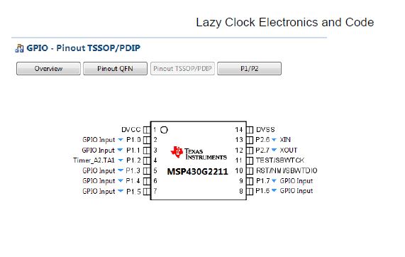
If I understand this correctly, it will simply use the same pin as the original code and will active the first solenoid, not the second once. However, I am notclear how to set up the second pin for the second coil. This is the Grace screen for the pins, if that helps:

Thank you.

James.


  • Hello James,

    Your Grace screenshot didn't make it to your post. Could you try it again?

    regards,
    JH

  • JH,


    I had not realised: thanks. Here is the missing image. 


    Thanks

    James.

  • James,

    P1SEL is a select function register meaning your giving a value of 1 (P1SEL |= BITx) as output or 0 (P1SEL &= ~BITx) as input. You may used another pin aside from P1.2 that also has a Timer Function Register.
  • I fear it isn't that simple.
    PxSEL is, as stated by Ryan, a register that controls the usage of port pins. Setting a bit in this register, means that the corresponding port pin is switched form GPIO function to its secondary module function.

    Pin 2 of port 1 is the Timer 2 CCR1 compare output signal. The signal is produced by the TimerA2.CCR1 capture/compare unit. To make a second control output, you would need to pick another pin that is the output of a different CCR unit, and then program its timer accordingly. The existing code won't be able to handle this. And depending on the timings, it won't even be possible to use the same timer for both.

    I suggest reading the users guide chapters about clock generation (for the timer clock base), digital I/O (pin configuration) and timers.

**Attention** This is a public forum