This thread has been locked.

If you have a related question, please click the "Ask a related question" button in the top right corner. The newly created question will be automatically linked to this question.

Debugging and understanding MSP432 pcm_go_to_lpm3 example

Guru 18595 points
Other Parts Discussed in Thread: ENERGYTRACE

Good morning!

I have just started with my MSP432 launchpad. I may be assuming some things wrong from my past experiences, so somehow my first attempts with this MCU are being a little confusing. Let's see if you can help me with these, I assume so, simple questions :)

This is the code, extracted most of it from TI Resource Explorer:

/*******************************************************************************
 * MSP432 PCM - Going to LPM3
 *
 * Description: In this very simple example, the use of the PCM API to go to
 * LPM3 is demonstrated. The device is configured for GPIO interrupt
 * (to wake the device up when the user presses the button on P1.1) and then
 * the device is put into LPM3 using the PCM_gotoLPM3 function.
 *
 *                MSP432P401
 *             ------------------
 *         /|\|                  |
 *          | |                  |
 *          --|RST         P1.0  |---> P1.0 LED
 *            |                  |
 *            |            P1.1  |<--Toggle Switch
 *            |                  |
 *            |                  |
 *
 * Author: Timothy Logan
 *******************************************************************************/
/* DriverLib Includes */
#include "driverlib.h"

/* Standard Includes */
#include <stdint.h>

#include <stdbool.h>

int main(void)
{
    /* Halting the Watchdog */
    MAP_WDT_A_holdTimer();

    /* Configuring P1.0 as output */
    MAP_GPIO_setAsOutputPin(GPIO_PORT_P1, GPIO_PIN0);

    /* Configuring P1.1 as an input and enabling interrupts */
    MAP_GPIO_setAsInputPinWithPullUpResistor(GPIO_PORT_P1, GPIO_PIN1);
    MAP_GPIO_clearInterruptFlag(GPIO_PORT_P1, GPIO_PIN1);
    MAP_GPIO_enableInterrupt(GPIO_PORT_P1, GPIO_PIN1);
    MAP_Interrupt_enableInterrupt(INT_PORT1);
    MAP_Interrupt_enableSleepOnIsrExit();
    
    /* Enabling MASTER interrupts */
    MAP_Interrupt_enableMaster();   

    /* Going to LPM3 */
    while (1)
    {
        MAP_PCM_gotoLPM3();
    }
}

/* GPIO ISR */
void gpio_isr(void)
{
    uint32_t status;
    volatile uint32_t i;

    status = MAP_GPIO_getEnabledInterruptStatus(GPIO_PORT_P1);
    MAP_GPIO_clearInterruptFlag(GPIO_PORT_P1, status);

    /* Toggling the output on the LED */
    if(status & GPIO_PIN1)
    {
        MAP_GPIO_toggleOutputOnPin(GPIO_PORT_P1, GPIO_PIN0);
        for(i = 0; i < 10000; i++);
    }

}

My first question is:

Since this is a power conservative example from TI, why aren't the unused pins and ports of MSP432 configured as low-level output?

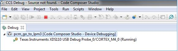
My second question is:

This code works well when I debug in CCS. However, when I stop the debugging session and run the code just by powering the launchpad, after some button presses, pauses and / or long presses, the code seems to freeze and the LED does not toggle anymore.
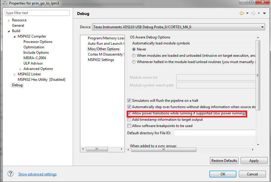
Last question is:

If I'm going into LPM modes, should I activate the "allow power transitions while running if supported" option?

I'm continuously checking the CCS for MSP432 manual but please let me know of any MSP430-like assumptions I have to get rid of for MSP432, if any. I'm probably assuming something or omitting something.

Have a really nice day!

  • Kazola,

    For the first part of your question we actually have updated this in the code example, however it is set to be released in the next version of DriverLib. In the meantime, I have attached the updated code example to this post. This will configure the ports/power/clock to optimize power consumption.

    One additional issue to note is that there is an outstanding problem that causes the ROM version of the following function not to be effective:

    MAP_Interrupt_enableSleepOnIsrExit();

    ... instead, replace that line with the following:

    Interrupt_enableSleepOnIsrExit();

    This will also be fixed in the next release and is simply an issue with how the rom.h file was generated.

    As for your issue about the code working/failing with the debugger connected/disconnected, I also see this behavior and have inquired internally.  It appears to be an issue isolated to CCS with how LPM3 transitions are handled  (the same code works without issue in IAR), but I will let you know when I get details for certain. Adding the fixed Interrupt_enableSleepOnIsrExit() line will actually mask this issue (as the processor will never wake up from LPM3 outside the ISR), but I will get you a more concrete solution when I know more.

    /*******************************************************************************
     * MSP432 PCM - Going to LPM3
     *
     * Description: In this very simple example, the use of the PCM API to go to
     * LPM3 is demonstrated. The device is configured for GPIO interrupt
     * (to wake the device up when the user presses the button on P1.1) and then
     * the device is put into LPM3 using the PCM_gotoLPM3 function. Furthermore,
     * the device is configured in a manner to minimize power consumption and
     * achieve datasheet specifications with regard to power consumption.
     *
     *                MSP432P401
     *             ------------------
     *         /|\|                  |
     *          | |                  |
     *          --|RST         P1.0  |---> P1.0 LED
     *            |                  |
     *            |            P1.1  |<--Toggle Switch
     *            |                  |
     *            |                  |
     *
     * Author: Timothy Logan
     ******************************************************************************/
    /* DriverLib Includes */
    #include "driverlib.h"
    
    /* Standard Includes */
    #include <stdint.h>
    
    #include <stdbool.h>
    
    int main(void)
    {
        /* Halting the Watchdog */
        MAP_WDT_A_holdTimer();
    
        /* Terminating all unused  pins to minimize power consumption. This is
            done by register accesses for simplicity and to minimize branching API
            calls */
        DIO->rPADIR.r = 0xFFFF;
        DIO->rPBDIR.r = 0xFFFF;
        DIO->rPCDIR.r = 0xFFFF;
        DIO->rPDDIR.r = 0xFFFF;
        DIO->rPEDIR.r = 0xFFFF;
        DIO->rPAOUT.r  = 0;
        DIO->rPBOUT.r = 0;
        DIO->rPCOUT.r = 0;
        DIO->rPDOUT.r = 0;
        DIO->rPEOUT.r = 0;
    
        /* Configuring P1.1 as an input and enabling interrupts */
        MAP_GPIO_setAsInputPinWithPullUpResistor(GPIO_PORT_P1, GPIO_PIN1);
        MAP_GPIO_clearInterruptFlag(GPIO_PORT_P1, GPIO_PIN1);
        MAP_GPIO_enableInterrupt(GPIO_PORT_P1, GPIO_PIN1);
        MAP_Interrupt_enableInterrupt(INT_PORT1);
        Interrupt_enableSleepOnIsrExit();
    
        /* Starting LFXT and sourcing ACLK and BCLK from it */
        MAP_CS_setExternalClockSourceFrequency(32000,48000000);
        MAP_GPIO_setAsPeripheralModuleFunctionOutputPin(GPIO_PORT_PJ,
                GPIO_PIN0 | GPIO_PIN1, GPIO_PRIMARY_MODULE_FUNCTION);
        MAP_CS_startLFXT(false);
        MAP_CS_initClockSignal(CS_ACLK, CS_LFXTCLK_SELECT, CS_CLOCK_DIVIDER_1);
        MAP_CS_initClockSignal(CS_BCLK, CS_LFXTCLK_SELECT, CS_CLOCK_DIVIDER_1);
    
        /* Disabling high side voltage monitor/supervisor */
        MAP_PSS_disableHighSide();
    
        /* Enabling "rude" mode which forces device to go to sleep regardless of
         * outstanding clock requests
         */
        MAP_PCM_enableRudeMode();
    
        /* Enabling MASTER interrupts */
        MAP_Interrupt_enableMaster();
    
        /* Going to LPM3 */
        while (1)
        {
            MAP_PCM_gotoLPM3();
        }
    }
    
    /* GPIO ISR */
    void gpio_isr(void)
    {
        uint32_t status;
    
        status = MAP_GPIO_getEnabledInterruptStatus(GPIO_PORT_P1);
        MAP_GPIO_clearInterruptFlag(GPIO_PORT_P1, status);
    
        /* Toggling the output on the LED */
        if(status & GPIO_PIN1)
        {
            MAP_GPIO_toggleOutputOnPin(GPIO_PORT_P1, GPIO_PIN0);
        }
    
    }


    Best Regards,

  • Nice answer Timothy! Thanks a lot :)

    One last question prior marking this thread as solved: 

    I'm seeing some strange behavior with EnergyTrace and MSP432. Even sometimes it counts down from negative time! Graphs are not plotting correctly, it takes about 5 seconds to start.... are all these related to any of the previous issues?

    Please let me know :)

  • Hi Timothy,
    may be one of this issues causing also EnergyTrace displaying even negative times? In other words, it displays -24, -23, -22... once started.
  • kazola,

    It's possible, however I need to consult with an energy trace expert before I can say for certain. One way to check would be to add that updated sleep after ISR exit line and see if the EngergyTrace works. I will inquire.

    Best Regards,
  • Kazola,

    I was able to spend some time debugging this and found a proper answer. First off, with the current version of silicon, when LPM3 is entered  only one SRAM bank retains its contents in memory by default. Since in the code examples we place the stack at the top of SRAM (good embedded practice), we run into problems when entering into LPM3 and end up corrupting the stack pointer. To fix this, simply add the following line to your code:

        /* Enabling SRAM Bank Retention for all banks */
        MAP_SysCtl_enableSRAMBankRetention(
                SYSCTL_SRAM_BANK1 | SYSCTL_SRAM_BANK2 | SYSCTL_SRAM_BANK3
                        | SYSCTL_SRAM_BANK4 | SYSCTL_SRAM_BANK5 | SYSCTL_SRAM_BANK6
                        | SYSCTL_SRAM_BANK7);

    This will ensure that all SRAM banks have retention enabled when entering LPM3. This will fix the issues you were seeing about the code not working without the debugger connected. Note that this will be fixed on the next version of the silicon so that all SRAM banks have LPM3 retention enabled by default.

    Also note that in order to enable LPM3 transitions with the debugger connected, you have to specifically enable this setting in the debug menu for XDS110:

    ... without this mode enabled, when debugging through CCS and entering  LPM3, the debugger will actually only go to LPM0 (which may explain the behavior that you see with EnergyTrace). Enabling this option will make it so the device truly goes into LPM3.

    With this option enabled, in the current CCS (6.1.0.00104), there is an issue that once you download the code you have to go through some additional steps to get the program running. Once you click debug, the code will download, however you will not be halted at main.

    In this case, you want to click the "Texas Instruments XDS110 USB Debug Probe_0/CORTEX_M4_0 (Running)" branch, pause the debugger (which will show your program counter sitting at the start of main), and then resume execution. After you do these steps, CCS will be running with true LPM3 transitions enabled. I am talking to the relevant people internally to get this process simplified in the future. 

    This should solve your original problem with the program not working without the debugger and hopefully solve the quirkiness you've been seeing with EnergyTrace and LPM3. Let me know if you have any additional questions. 

    Best Regards,

  • Hi Timothy,

    Thanks for your time. I'm marking this as solved!

    I will keep posting similar issues, if any, just in case they can be as useful as this one :)

    Have a nice day!

  • Hi Timothy,

    Do you know if there is a similar option in IAR?

    I tried your example but also enabled the ACLK, SMCLK and MCLK on the port pins.

    My idea was to monitor the DCO clock being shut down for the period spent in LPM3.

    However, MCLK is present on the port pins  even during LPM3 which indicates the MCU is not in LPM3.

    The behaviour is identical in my test program where I am trying to exercise the MCU through most of its power/frequency modes.

    Many thanks in advance,

    Dimo 

**Attention** This is a public forum