This thread has been locked.

If you have a related question, please click the "Ask a related question" button in the top right corner. The newly created question will be automatically linked to this question.

how to use FRAM's IPE

in the FRAM,IPE is used for  Intellectual Property,refer to FRAM's User Guid,when powered up,MCU will first excute boot code,boot code will prelaod user-defined setting in which we can write IPE Regisitor,after that,IPE code eara can be protected. TI has give examples how to realize it using CCS,if I use IAR,what can i do to realize it .

  • There is some more information here: www.ti.com/.../slaa628.pdf

    You may have to port the examples yourself. Do you have a link for the examples?
  • It looks like IAR supports this in 6.10 and beyond: www.iar.com/.../product-news

    I would reference the IAR documentation to see what it says.
  • // This is the project dependent part
    // Modify where you want the start and end address for IPE segment
    #define IPE_START 0x04400 // This defines the Start of the IP protected area
    #define IPE_END 0x04800 // This defines the End of the IP protected area

    /*
    * Do not change this section - BEGIN
    */

    // Hardcoded memory signature location
    #define IPE_SIG_VALID 0xFF88 // IPE signature valid flag
    #define IPE_STR_PTR_SRC 0xFF8A // Source for pointer (nibble address) to MPU IPE structure

    // Define the IPE signature location to 0xAAAA @ 0xFF88 to enable IPE
    #pragma RETAIN(ipe_signalValid)
    #pragma location=IPE_SIG_VALID
    const unsigned int ipe_signalValid = 0xAAAA;

    /*
    Locate your IPE structure and it should be placed on the top of the IPE memory. In this example, IPE structure is at 0x4400
    */

    #pragma RETAIN(IPE_stringPointerSourceSource)
    #pragma location=IPE_STR_PTR_SRC
    const unsigned int IPE_stringPointerSourceSource = ((IPE_START)) >> 4;
    // IPE data structures definition, reusable for ALL projects
    #define IPE_SEGREG(a) (a >> 4)
    #define IPE_BIP(a,b,c) (a ^ b ^ c ^ 0xFFFF)
    #define IPE_FILLSTRUCT(a,b,c){a,IPE_SEGREG(b),IPE_SEGREG(c),IPE_BIP(a,IPE_SEGREG(b),IPE_SEGREG(c))}

    typedef struct IPE_Init_Structure {
    unsigned int MPUIPC0 ;
    unsigned int MPUIPB2 ;
    unsigned int MPUIPB1 ;
    unsigned int MPUCHECK ;
    } IPE_Init_Structure; // this struct should be placed inside IPB1/IPB2 boundaries


    // Ensures the compiler do not optimize the structure since it is not called by the application
    #pragma RETAIN(ipe_configStructure)

    // IPE is defined in an adopted linker control file
    #pragma DATA_SECTION(ipe_configStructure,".ipestruct");

    // IPE is the section for protected data;
    const IPE_Init_Structure ipe_configStructure = IPE_FILLSTRUCT(MPUIPLOCK + MPUIPENA,
    IPE_END,IPE_START);

    /*
    * Do not change this section - END
    */

    // An example on how to place code inside the IPE region
    #pragma SET_CODE_SECTION(".ipe")
    extern void blinkLedFast(void);
    extern void blinkLedSlow(void);
    #pragma SET_CODE_SECTION()


    TI has released a examples to realize IPE feature using CCS,what i can do to realize IPE in IAR refer to this code ?

    And how should i use the code above to realize the IPE in CCS?is there any detailed referenece to do that step by step?

    Another question:
    if i have realized IPE features in my code,Does it means that IPE will take action after the code firsted being loaded to FRAM,for example,if my FRAM has not being powered up,whether we can access the IPE eara Code using other physical method such as dissecting the IC
  • My understanding is, you can make your code and constants in part of the FRAM executable but not readable. In order to do that, you need to write a certain data pattern at certain locations (as described in the User’s Guide). The first time a BOR happens, the boot code will pick up those data and make your wish become true.

    The requirement is very simple. You should be able to do it even with almost “bare hand” -- such as a text editor and either BSL or MSP430Flasher. I have no doubt that both IAR or CCS can do it.
  • My understanding is, you can make your code and constants in part of the FRAM executable but not readable. In order to do that, you need to write a certain data pattern at certain locations (as described in the User’s Guide). The first time a BOR happens, the boot code will pick up those data and make your wish become true.

    The requirement is very simple. You should be able to do it even with almost “bare hand” -- such as a text editor and either BSL or MSP430Flasher. I have no doubt that both IAR or CCS can do it.

  • i know what you mean,after 0xAAAA has been write to 0xFF88,the boot code will jump to 0xFF8A to execute, 0xFF8A is the start address of IPE configure structure,but the question is how to locate IPE configure structure at 0xFF8A
  • Hi guys,

    This is actually easier now than it would look from the documentation. The doc is showing how to do it by hand. But you can let CCS/IAR do almost all of the IPE setup (init the structure and everything) itself.

    Here's what I do in CCS to enable it:

    1. Every function that I want to place in the IPE section, I use #pragma CODE_SECTION(foo, ".ipe") to place it in the IPE section (may have to be a bit different pragma in IAR). The linker file has already defined an IPE section. Do the same thing for ISRs you want to encapsulate but put them in ".ipe:_isr"

    2. In the project > properties > General under the MSP430 IPE tab, select "Enable Intellectual Property Encapsulation", and select "Let compiler handle IPE memory partitioning based on user-code and data placement.

    If you do this, now what happens is the compiler will actually do all of the IPE register initialization for you! You don't have to set up the structure or anything. What happens is that the compiler will use a boot_special.c in the run-time support library instead of the normal boot c-startup code, and this includes setting up the structure and IPE registers for you. It determines the IPE register settings by knowing what address space that ipe section in the linker file is taking up when it builds. This makes everything quite simple.

    Please note that once you enable IPE, to be able to reprogram the part and be able to reprogram things in that area, you will have to tell CCS to do a special erase to erase the IPE area - you can do this under Project > Properties > Debug > MSP430 Properties and setting under "Connection options" to "On connect, erase main, information, and IP protected area". This will have it wipe the whole part so that you can actually program it again including that area.

    I believe that IAR has an equivalent of all of this - the pragma will be different (use "location" probably), and the linker file segment names are probably different, but that should be explained in the IAR user's guide. It also has this similar tool to just select IPE to be enabled in it when you use this to put your code in the right section as well.

    As a note, I think we're working to make some examples and doc of how to use the IPE to make this clearer and easier for people.
     
    Regards,
    Katie

  • You can put that "IPE configure structure" at any otherwise unused FRAM in the "lower 64KB" address space. Put a 16-bit pointer to that structure at 0xFF8A.

    After BOR, all the above can be scratched and those FRAM locations can be reused.
  • hello,Katie
    it is very necessary for TI to release some docs about how to use IPE, both in CCS and IAR.
    in IAR, i know how to enable IPE,but in IAR the IPE border and IPE structure are defined by the IAR, and how can we set IPE border and IPE structure munually? and how to locate user guid to the IPE eara?

    thanks
    Kissn
  • Hi Kissn,

    I posted an answer in your other thread here: e2e.ti.com/.../1532612
    It is pretty easy to change where the IPE area starts in IAR by simply modifying IPE_B1= in the linker file. Then you can still like IAR set up the IPE init structure for you, but control the address where it places the IPE sections.

    -Katie
  • old_cow_yellow said:

    ... In order to do that, you need to write a certain data pattern at certain locations (as described in the User’s Guide). The first time a BOR happens, the boot code will pick up those data and make your wish become true.

    ...

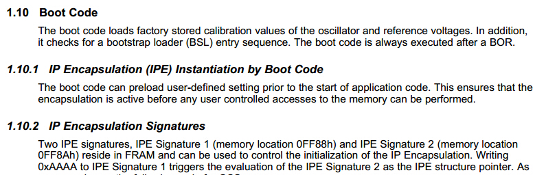
    I want to retract that. I now strongly suspect that Sections 1.10.1, 1.10.2, and 1.10.3 in that User's Guide are not applicable, obsolete, or erroneous.

    I suspect that the MPUIPLOCK bit in the MPUIPC0 register can be set to 1 by user code but can only be cleared to 0 by a special erase that also erases the contends of all the FRAM. (This also contradicts to the User's Guide which says it will be cleared to 0 by BOR).

    --OCY

  • Hi OCY,

    To my knowledge these sections are still applicable, but letting the tool do all the setup is just much easier than implementing it by hand this way. Basically it is doing the same thing as described in those user's guide sections, but it's doing it for you behind-the-scenes instead of you having to set up a structure yourself by hand. So I think having the information in the user's guide is useful, but should be presented more as a "here's how it works" and less as being the way you have to implement it - it should recommend you to use the tool.

    If you examine the linker cmd file in the latest versions of CCS, you can see at the bottom of the file a section starting with #ifdef _IPE_ENABLE. If you have enabled IPE in your project settings, this is defined. Then the following statements evaluate your settings options that you may have set in the tool, determine/calculate the borders of the IPE area based on code you placed in the IPE sections, and then figures out the address for where to put the IPE structure and calculates the struct checksum. So then the linker can place this structure in FRAM with all the information when you build.

    If you view the .map file generated when you build with this IPE enabled in the project properties, you can see where it has placed the ipestruct, and that it is 8 bytes long (just as described in section 1.10.3). If you then look at this address in the TI-txt binary file generated by building the project, you should be able to see what values it has but in the ipestruct.

    In addition, you can see that the ipesignature has been defined as well, and also view it in the TI-txt file starting at 0xFF88. Signature 2 at 0xFF8A contains the address of the ipestruct right shifted by 4 bits. So it is pretty interesting to look at the TI-txt file and see how simply enabling the IPE it does all of this initialization at these addresses for the struct and IPE signatures for you. So basically it's all doing exactly what is described in those user's guide sections, but you don't have to implement that code yourself.

    I do think that the user's guide does need to be updated to point out that you don't have to do all of this by hand anymore and can use the tool instead, and to make clear that these sections are just explaining how it could be done by hand and/or what happens behind-the-scenes. I have filed this as an enhancement on the docs.


    old_cow_yellow said:
    I suspect that the MPUIPLOCK bit in the MPUIPC0 register can be set to 1 by user code but can only be cleared to 0 by a special erase that also erases the contends of all the FRAM. (This also contradicts to the User's Guide which says it will be cleared to 0 by BOR).

    About the MPUIPLOCK bit in the MPUIPC0 register, you can see section 7.5 "MPUIPLOCK allows to separately lock the MPUIPC0 and MPUIPSEGBx registers. Write access is not possible on these registers until a BOR occurs. MPUIPLOCK cannot be cleared manually" Now in addition, while BOR does clear this bit to 0, what happens is that per section 1.10.1 the boot code preloads the IPE settings before any user code/memory accesses can be performed. So, if you have a valid IPE structure already set with the bootcode pointing to it (from trapdoor mechanism mentioned in 1.10.2.1), then the bootcode is going to load that MPUIPC0 definition from the structure into the register before you get to any code execution, so MPUIPLOCK will be set (if it's set in your structure). So effectively, it's kind of the same thing that you described, because while the bit is set to 0 on BOR, it won't stay cleared as long as the IPE is still in place because the structure will re-initialize it from boot code, and you'll only really be able to clear it and have it stay cleared after the boot code, if you do the special erase to erase the IPE completely.

    Regards,

    Katie

  • i want to know whether TI has release  detail application docs about how to use IPE both in IAR and CCS?

    i think it is very import because this feature is very import but many people do not know how to realize it in their project including me.

    thanks

    kissn Liu

  • Hi Kissn,

    I've actually personally already been working to make some example/documentation about this feature because we have realized there is a gap here, along with a few other related topics, but I can't give an estimated timeline of when that will be released yet.

    There is some information already in documentation - for now the best places to look are:
    1. CCSv6.1 user's guide: www.ti.com/lit/pdf/slau157 there is a section on the IPE setup in CCS.
    2. IAR EW430_CompilerReference (found in your IAR installation and also found on the web)

    However we do realize that we need to make an example to try to make this more accessible to people rather than just the information in these docs.

    Regards,
    Katie

  • Thanks,so can you send what you have do to my email.my email address is m852523899@163.com
  • Hi Kissn,

    The materials are not ready for release yet. However my comments on this thread, as well as the two documents I just pointed you to, should have the information you need to get started.

    Regards,
    Katie
  • Really you do not need anything extra in your code - no init structure or anything. Simply take any functions that you want to put in the IPE area, and do this for each of them in CCS:

    #pragma CODE_SECTION(encapsulated_blink, ".ipe")
    void encapsulated_blink(void)
    {

    And then set IPE enabled in the project setting.

    For IAR, do this:

    #pragma location = "IPECODE16"
    void encapsulated_blink(void)
    {

    And then set IPE enabled in the project setting. That's really all that you have to do to get things put in the IPE area, and the IDE will do everything else automatically without having to modify your code (setting up init structure, writing the IPE signatures - this is all done for you).

    There's more information about IPE for IAR in the IAR EW430 compiler reference, and for CCS in the CCS user's guide.

    Finally, it's up to you to make sure that whatever code you put into the IPE section is not introducing vulnerabilities either of course - must use good coding practice.

    Regards,

    Katie 

  • Katie Pier said:

    Hi OCY,

    To my knowledge these sections are still applicable, but letting the tool do all the setup is just much easier than implementing it by hand this way. ...

    About the MPUIPLOCK bit in the MPUIPC0 register, you can see section 7.5 "MPUIPLOCK allows to separately lock the MPUIPC0 and MPUIPSEGBx registers. Write access is not possible on these registers until a BOR occurs. ...

    You are right (again ;). I misunderstood a few details in the User's Guide. After reading it again, I succeeded in "doing it by hand". It turns our to be very simple to do. To me, that is more satisfying then let someone or something to do it for me.

    Thanks you, Katie.

  • 1. These days i am trying to use IPE in the IAR.and there is question,if i have enabled IPE in my program and get a txt file that can be downloaded to MSP430 via promgram tools (JTAG has not been protected by password),i know that when IPE has been enabled,the code cannot be read out,but could i disable IPE(erase IPE configure structure) through program tools via JTAG method and reprogram it?

    2. Another question,in my program if i erase IPE signature (0xFF88),does it mean that IPE protection is not exsit after PUR or BOR?
  • 1. I know that MSP430Flasher is capable of removing IPE with "-e ERASE_TOTAL". I suppose IAR and CCS can to that too.

    2. No. Once IPE is enabled, the contends of 0xFF88-FF8B can be changed without any effects on IPE.

    On the other hand, IPE could have included self-destruct or self-modify features built-in.
  • hi,I have a question to disscus:
    if i have protected my code through IPE,and the Interrupt vector 0xFF80-0xFFFF is inside the IPE eara,so after JTAG has been prohibit through JTAG password,if i want to access msp430 again through JTAG,i have to erase JTAG password through BSL,but BSL can not remove IPE protected fuction,does it mean that i can no longer access this MSP430 through JTAG forever,thus IPE eara can no longer be erased???
  • 0xFF80-0xFFFF can still be read/written outside of IPE even if that address range is within the IPE limits.

    Yes, if you disabled both JTAG, BSL and your own code cannot change them, you will be stuck in that situation. But this has nothing to do with IPE.
  • I wanted to share for anyone finding this thread in the future - we just released the app note with code and detailed examples of enabling IP Encapsulation using the tools built into CCS and IAR. www.ti.com/.../slaa685 www.ti.com/.../slaa685

**Attention** This is a public forum