This thread has been locked.

If you have a related question, please click the "Ask a related question" button in the top right corner. The newly created question will be automatically linked to this question.

I2041 SD24 Exception

Other Parts Discussed in Thread: MSP430I2041, MSP-FET

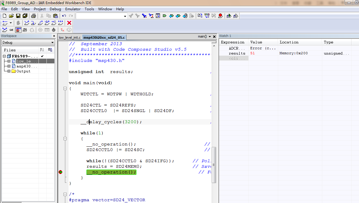
i used circuit above to test SD24 precision,but when tie A0.0+ to A0.0- ,there is a drift about 24/65536*1.16 = 0.4mv in my result, why this happens?

  • Kissn Liu,

    There certainly should not be this much of an offset/drift on the SD24 of the MSP430i2041, especially if the low_level_init function is properly being included in your project (for calibration purposes).

    I modified one of the simple code examples (attached below) to save the values in a buffer in RAM. Additionally, I was testing using the MSP-TS430PW28B target board with the MSP-FET emulator connected for debugging. Using this code, I was not seeing any value outside the range of 0xFFF4 to 0xFFF6. I have also attached my output data file from the RAM buffer I mentioned previously.

    Can you provide similar data for me to see your drift?

    /* --COPYRIGHT--,BSD_EX
     * Copyright (c) 2013, Texas Instruments Incorporated
     * All rights reserved.
     *
     * Redistribution and use in source and binary forms, with or without
     * modification, are permitted provided that the following conditions
     * are met:
     *
     * *  Redistributions of source code must retain the above copyright
     *    notice, this list of conditions and the following disclaimer.
     *
     * *  Redistributions in binary form must reproduce the above copyright
     *    notice, this list of conditions and the following disclaimer in the
     *    documentation and/or other materials provided with the distribution.
     *
     * *  Neither the name of Texas Instruments Incorporated nor the names of
     *    its contributors may be used to endorse or promote products derived
     *    from this software without specific prior written permission.
     *
     * THIS SOFTWARE IS PROVIDED BY THE COPYRIGHT HOLDERS AND CONTRIBUTORS "AS IS"
     * AND ANY EXPRESS OR IMPLIED WARRANTIES, INCLUDING, BUT NOT LIMITED TO,
     * THE IMPLIED WARRANTIES OF MERCHANTABILITY AND FITNESS FOR A PARTICULAR
     * PURPOSE ARE DISCLAIMED. IN NO EVENT SHALL THE COPYRIGHT OWNER OR
     * CONTRIBUTORS BE LIABLE FOR ANY DIRECT, INDIRECT, INCIDENTAL, SPECIAL,
     * EXEMPLARY, OR CONSEQUENTIAL DAMAGES (INCLUDING, BUT NOT LIMITED TO,
     * PROCUREMENT OF SUBSTITUTE GOODS OR SERVICES; LOSS OF USE, DATA, OR PROFITS;
     * OR BUSINESS INTERRUPTION) HOWEVER CAUSED AND ON ANY THEORY OF LIABILITY,
     * WHETHER IN CONTRACT, STRICT LIABILITY, OR TORT (INCLUDING NEGLIGENCE OR
     * OTHERWISE) ARISING IN ANY WAY OUT OF THE USE OF THIS SOFTWARE,
     * EVEN IF ADVISED OF THE POSSIBILITY OF SUCH DAMAGE.
     *
     *******************************************************************************
     * 
     *                       MSP430 CODE EXAMPLE DISCLAIMER
     *
     * MSP430 code examples are self-contained low-level programs that typically
     * demonstrate a single peripheral function or device feature in a highly
     * concise manner. For this the code may rely on the device's power-on default
     * register values and settings such as the clock configuration and care must
     * be taken when combining code from several examples to avoid potential side
     * effects. Also see www.ti.com/grace for a GUI- and www.ti.com/msp430ware
     * for an API functional library-approach to peripheral configuration.
     *
     * --/COPYRIGHT--*/
    //******************************************************************************
    //  MSP430i20xx Demo - SD24, Single Conversion on a Single Channel, Use ISR
    //
    //  Description: This program uses the SD24 module to perform a single
    //  conversion on a single channel. A SD24 interrupt occurs when a conversion
    //  has completed.
    //
    //  Test by applying a voltage to the input channel and setting a breakpoint
    //  at the indicated line. Run program until it reaches the breakpoint, then use
    //  the debugger's watch window to view the conversion results.
    //
    //  Results (upper 16 bits only) are stored in the variable "results"
    //
    //  ACLK = 32kHz, MCLK = SMCLK = Calibrated DCO = 16.384MHz, SD_CLK = 1.024MHz
    //  * Ensure low_level_init.c is included when building/running this example *
    //
    //  Notes: For minimum Vcc required for SD24 module - see datasheet
    //         100nF cap btw Vref and AVss is recommended when using 1.2V ref
    //
    //               MSP430i20xx
    //             -----------------
    //         /|\|                |
    //          | |                |
    //          --|RST             |
    //            |                |
    //   Vin1+ -->|A0.0+      VREF |---+
    //   Vin1- -->|A0.0-           |   |
    //            |                |  -+- 100nF
    //            |                |  -+-
    //            |                |   |
    //            |           AVss |---+
    //
    //  T. Witt
    //  Texas Instruments, Inc
    //  September 2013
    //  Built with Code Composer Studio v5.5
    //******************************************************************************
    #include "msp430.h"
    
    #define BUFFER_SIZE 256
    
    unsigned int results[BUFFER_SIZE];              // SD24 Conversion Result Buffer
    unsigned int index = 0;                         // Buffer index
    
    void main(void) {
        WDTCTL = WDTPW | WDTHOLD;                   // Stop WDT
    
        SD24CTL = SD24REFS;                         // Internal ref
        SD24CCTL0  |= SD24SNGL | SD24DF | SD24IE;   // Enable interrupt
    
        __delay_cycles(3200);                       // Delay ~200us for 1.2V ref to settle
    
        while(1) {
            SD24CCTL0 |= SD24SC;                    // Set bit to start conversion
            __bis_SR_register(LPM0_bits | GIE);     // Enter LPM0 w/ interrupts
            __no_operation();                       // For debugger
    
            if(index > (BUFFER_SIZE - 1)) {         // If index has reached end of buffer
            	index = 0;                          // Reset index
            	__no_operation();                   // SET BREAKPOINT HERE
            }
        }
    }
    
    #if defined(__TI_COMPILER_VERSION__) || defined(__IAR_SYSTEMS_ICC__)
    #pragma vector=SD24_VECTOR
    __interrupt void SD24_ISR(void) {
    #elif defined(__GNUC__)
    void __attribute__ ((interrupt(SD24_VECTOR))) SD24_ISR (void)
    #else
    #error Compiler not supported!
    #endif
        switch (__even_in_range(SD24IV,SD24IV_SD24MEM3)) {
            case SD24IV_NONE: break;
            case SD24IV_SD24OVIFG: break;
            case SD24IV_SD24MEM0:
                       results[index++] = SD24MEM0; // Save CH0 results (clears IFG)
                       break;
            case SD24IV_SD24MEM1: break;
            case SD24IV_SD24MEM2: break;
            case SD24IV_SD24MEM3: break;
            default: break;
        }
        __bic_SR_register_on_exit(LPM0_bits);       // Wake up from LPM0
    }
    

    DC.BIAS.dat

  • yes,i have included __low_level_init.c into my project,but the drift still exist,did you tie the A0+、A0- togther while testing???
  • Kissn Liu,

    Yes, I have jumpered both of these inputs to the GND pins on J5 on the MSP-TS430PW28B target board.

    Are you running on a custom PCB, an EVM, or a target board?
  • i am running on a target board, just like the circuit above, and the result remain 24 with no change.can you give me your circuit,thank you
  • Kissn Liu,

    Attached below is the schematic for the target board. I have connected pins 1 & 2 (A0.0+ and A0.0-) to the GND pins of J5.

    This emulates exactly what you are showing on your schematic.

    MSP-TS430PW28B_schematic.pdf

  • and there is a anther phenomenon,when there is a resistance between A0+ and A0- with A0- jumped to ground, the drift will become more obvious,for example ,if the resistance is 1kohm,the drift will be 51 with no change.
  • so the there is no difference bettween our circuit, can you give me some explans about why that happens?
  • Kissn Liu,

    Currently, I cannot think of a reason why there would be a difference.

    Can you confirm your results with the code I wrote and modified and then send me the results to ensure that the problem still exists?
  • >Currently, I cannot think of a reason why there would be a difference.
    Lost calibration data? After all datasheet specify 4mV offset error at gain=1.
  • i used your program above but the drift ( 24/65536*1.16 = 0.4mv)still exist, and will become serious when jumped a resistance between A0+ and A0-. when there is an OPA as input buffer before A0+(A0- jumped to ground ),this offest will lighten a little .
  • Did you check that information memory still contains factory calibration data? FYI SD24 trim calibration value address: 013DAh. For further information refer to "6.10.11 Device Descriptor" chapter of the datasheet
  • Kissn Liu,

    After reading through documentation further, I believe this can be contributed to the offset error of the converter, which is specified by the datasheet in section 6.6.7.

    The calibration that we run in low_level_init trims the reference delay (for the reference voltage buffer start up) and trims the bias current of the SD24. Even tweaking these parameters did not give me the offset error that you are seeing, which leads me to believe that it is an offset error intrinsic to that individual unit.

    That being said, taking this information and cross referencing with the DS (especially Table 6-22), shows that this is not outside of the specified operation of the converter.

**Attention** This is a public forum