This thread has been locked.

If you have a related question, please click the "Ask a related question" button in the top right corner. The newly created question will be automatically linked to this question.

MSP430F6736 DCO start- up time waking from LPM3?

Other Parts Discussed in Thread: MSP430F6736, MSP430WARE

Hello TI employee,

I'm working on  UART issue, I need the whole system sleep in LPM3 to save power consuption ,but I need it wake up form LPM3 and receive data from the UART bus(57600bps)as soon as possible, or the first byte will corrupt.  I remember the DCO of MSP430s can wake up from LPM4 in 5 us.  so I thinlk it 's  a piece of cake for  MSP430F6736 to do this job , The fact is it fails :( .  The first guess flash in my head is the Start-up time may be too long ,so I do the following experment.  

PJ.0 -----second fuction----SMCLK---output     souced   from DCO

P1.3  ----IO

#include "msp430F6736.h"
#include "HAL_PMM.h"

u16_t VcoreSettingFlag;
void init_SysClk(void)
{
    u08_t VcoreSettingFlag;
    
    PJSEL |=BIT0;
    PJDIR |= BIT0;
    
    // SetVCore()-----TI lib
    VcoreSettingFlag =SetVCore(PMMCOREV_3);
    if( VcoreSettingFlag==0)
    {
        // OK 
        _NOP();
        _NOP();
        
    }
    
    //刚开始设定晶振失效不会引起不可屏蔽中断
    SFRIE1 &=~OFIE;
    
    UCSCTL0 = 0;
    UCSCTL1 = DCORSEL_6;
    //FLLD =2  FLLN=255
    UCSCTL2 = FLLD_1 + 255;
    UCSCTL3 = 0;
    UCSCTL4 = SELA__XT1CLK + SELS__DCOCLK + SELM__DCOCLK;
    //UCSCTL4 = SELA__XT1CLK + SELS__DCOCLKDIV + SELM__DCOCLKDIV;
    
    //MCLK SMCLK ACLK都不分频
    UCSCTL5 = DIVM_0 + DIVS_0 + DIVA_0;
    
    //使用增强型驱动晶振快速起振
    UCSCTL6 = XT2OFF + XT1DRIVE_3;
    //进入LPMx之后直接关闭时钟  不允许模块有要求的时候 就不允许睡眠的情况
    UCSCTL8 &=~( ACLKREQEN | MCLKREQEN | SMCLKREQEN | MODOSCREQEN);
    UCSCTL8 |=SMCLKREQEN;
    
    do{
        UCSCTL7 &=~(XT2OFFG  | XT1LFOFFG | DCOFFG);
        SFRIFG1 &=~ OFIFG;
        __delay_cycles(1000);
    }while(SFRIFG1 & OFIFG);
    _NOP();
    _NOP();
    //跳出OFIFG检测循环后,需要延时一段时间,再次检测,
    //以充分认证晶振确实已经稳定工作
    __delay_cycles(1000);
    _NOP();
    //起振之后,可以关闭增强型驱动,以降低功耗。
    UCSCTL6 = XT2OFF;
    
    do{
        UCSCTL7 &=~(XT2OFFG  | XT1LFOFFG | DCOFFG);
        SFRIFG1 &=~ OFIFG;
        __delay_cycles(500);
    }while(SFRIFG1 & OFIFG);
    
    //设定晶振失效引起不可屏蔽中断
    //----第一次禁止是因为晶振刚开始工作,这个需要时间,晶振失效
    //导致相应的OFIFGG属于正常起振过程;但是晶振已经正常工作后,再次
    //晶振失效,这个就属于不正常现象,需要应用代码介入,具体处理
    //由用户自己决定
    SFRIE1 |=OFIE;
    _NOP();
    _EINT();
}

#pragma vector = PORT1_VECTOR
__interrupt void TxRxIo_Isr(void)
{
    P1IFG &=~(BIT2+BIT3);
    LPM3_EXIT;
}


void main( void )
{
    // Stop watchdog timer to prevent time out reset
    WDTCTL = WDTPW + WDTHOLD;
    init_SysClk();
    
    P1DIR &=~BIT3;
    P1SEL &= ~BIT3;
    P1IES |= BIT3;
    P1IE |= BIT3;
    
    while(1)
    {
        LPM3;;
        _NOP();
        _NOP();
        __delay_cycles(9999999);
        __delay_cycles(9999999);
        _NOP();
        _NOP();
    }
    
}

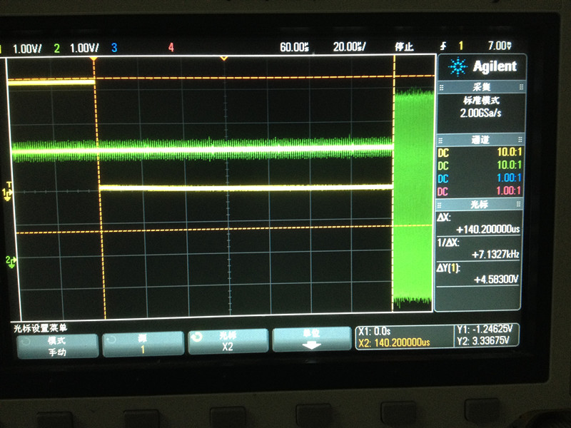
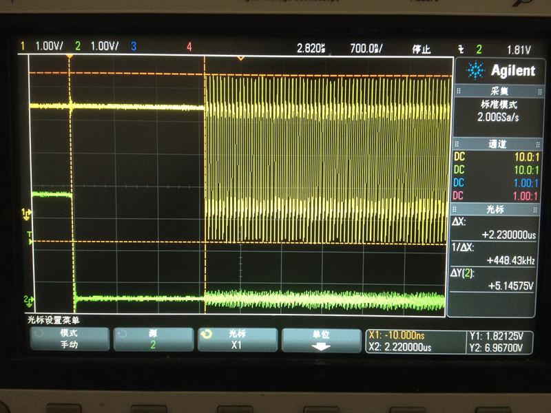
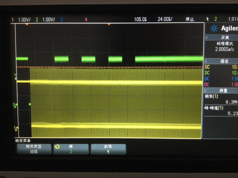
The yellow line is P1.3 , the green line is PJ.0 -----SMCLK

the result is that  DCO  nearly costs 140us  to start up,  Am I get sth wrong or I miss sth ?   Need your help , Thanks in advance.

  • Hi,

    I think the issue is your are not configuring the PMM for fast wakeup. The 140us you are seeing falls in line with the wake-up time from LPM2/3/4 datasheet spec for slow wakeup of 150us typical.

    I strongly encourage you to use the driverlib code for configuring the PMM. There are code examples for driverlib pmm code in the mspware section of the resource explorer in CCS.

    Mike
  • Hello Mike,
    Thanks for your answer. I have tried as you told me. It works when I enable the full-performance mode. However, another issue comes up .
    And still need your help. 


    Now DCO can start up in less than 3us after the falling edage of STATR bit . but the frequence of DCO decrease to 8MHz if the system enter into LPM3.

    I set DCO runs @~16.7MHz .

    The following is my test code :

    void main( void )
    {
        // Stop watchdog timer to prevent time out reset
        WDTCTL = WDTPW + WDTHOLD;
        init_SysClk();
        init_Uart();
       // while(1);
        while(1)
        {
            LPM3;
        }
      
    }
    
    u16_t VcoreSettingFlag;
    void init_SysClk(void)
    {
        u08_t VcoreSettingFlag;
        
        
        //PJ.0刚好是SMCL输出脚  注意在仿真的时候 不可以
        PJSEL |=BIT0;
        PJDIR |= BIT0;
        
        
        VcoreSettingFlag =SetVCore(PMMCOREV_3);
        if( VcoreSettingFlag==0)
        {
            //==0说明 内核电压改变正常
            _NOP();
            _NOP();
            
        }
        
        //刚开始设定晶振失效不会引起不可屏蔽中断
        SFRIE1 &=~OFIE;
        
        UCSCTL0 = 0;
        UCSCTL1 = DCORSEL_6;
        //FLLD =2  FLLN=255
       UCSCTL2 = FLLD_1 + 255;
        UCSCTL3 = 0;
        UCSCTL4 = SELA__XT1CLK + SELS__DCOCLK + SELM__DCOCLK;
       // UCSCTL4 = SELA__XT1CLK + SELS__DCOCLKDIV + SELM__DCOCLKDIV;
        
        //MCLK SMCLK ACLK都不分频
        UCSCTL5 = DIVM_0 + DIVS_0 + DIVA_0;
        
        //使用增强型驱动晶振快速起振
        UCSCTL6 = XT2OFF + XT1DRIVE_3;
        //进入LPMx之后直接关闭时钟  不允许模块有要求的时候 就不允许睡眠的情况
        UCSCTL8 &=~( ACLKREQEN | MCLKREQEN | SMCLKREQEN | MODOSCREQEN);
        UCSCTL8 |=SMCLKREQEN;
        
        do{
            UCSCTL7 &=~(XT2OFFG  | XT1LFOFFG | DCOFFG);
            SFRIFG1 &=~ OFIFG;
            __delay_cycles(1000);
        }while(SFRIFG1 & OFIFG);
        _NOP();
        _NOP();
        //跳出OFIFG检测循环后,需要延时一段时间,再次检测,
        //以充分认证晶振确实已经稳定工作
        __delay_cycles(1000);
        _NOP();
        //起振之后,可以关闭增强型驱动,以降低功耗。
        UCSCTL6 = XT2OFF;
        
        do{
            UCSCTL7 &=~(XT2OFFG  | XT1LFOFFG | DCOFFG);
            SFRIFG1 &=~ OFIFG;
            __delay_cycles(500);
        }while(SFRIFG1 & OFIFG);
        
        //设定晶振失效引起不可屏蔽中断
        //----第一次禁止是因为晶振刚开始工作,这个需要时间,晶振失效
        //导致相应的OFIFGG属于正常起振过程;但是晶振已经正常工作后,再次
        //晶振失效,这个就属于不正常现象,需要应用代码介入,具体处理
        //由用户自己决定
        SFRIE1 |=OFIE;
        _NOP();
        _EINT();
    }
    
    void init_Uart(void)
    {
        //();
        UART_FUCTION();
        
        UCA0CTLW0  |= UCSWRST;
        //SMCLK为UART的时钟源
        UCA0CTLW0  |= UCSSEL__SMCLK;
        // 57600
        UCA0CTLW1  = 0x03;
        UCA0BRW = 18;
        UCA0MCTLW = 0x4431;
        UCA0CTLW0 &=~UCSWRST;
        
        UCA0IE |= UCRXIE;
    }
    
    #pragma vector = USCI_A0_VECTOR
    __interrupt void Uart_Isr(void)
    {
        _NOP();
        _NOP();
        switch(UCA0IV )
        {
        case 0x00: break;
        
        //接收
        case 0x02:
    //        while ((UCA0IFG & UCTXIFG) == 0);
    //        UCA0TXBUF=UCA0RXBUF;  
            Buffer[k++] = UCA0RXBUF;
            if(k==5)
            {
                
                k=0;
                _NOP();
            }
          //  LPM3_EXIT;
            break;
            
            //发送
        case 0x04:
            break;
            
            //start bit
        case 0x06:
            _NOP();
            _NOP();
            break;
            
        case 0x08:
            break;
            
        default:break;
        
        }
    }

    The Green Line is P1.2(UCA0RXD)   Yellow Line ---PJ.0 (SMCLK)

    Which pulzzed me is that if I comment LPM3 , and use  while loop insead of LPM3 , the frequevce is become normal-----> ~16.7MHz.

    I checked the registers  of  UCS  before and after enter into LPM3 , they 're the same except UCSCTL0( I know its reasonable because of FLL cause.)

  • Dozens of experiments have made , All the clues directs to the DCO frequency issue.


    Before enter into LPM3 , DCO runs @~16.7Mhz. if a RX interrupt happens, wake the DCO from LPM3,

    the frequency decrease to nearly half of 16.7MHz(~8.3Mhz). Because the UART divder value is caculated based @16.7Mhz, 

    A 8.3MHz CLK ,of course , will cause a fault baudrate ,then a corrputed byte in RX buffer.
    FLL is enable default after power on ,but will disable in ISR. However, MOD and DCO bits in UCSCTL0
    keep the same when a interrupt happens before and after , the only difference is DCO will not follow the
    reference CLk(32768Hz), am I right?

    Which confuse me most is how does a 8.3MHz frequency come up? It's unreasonable.
    I set a 4.1MHz DCO intetionally then enter into LPM3. The falling edge of START bit wakes DCO up,
    however, the frequency becomes nearly ~2.7Mhz.

    So it maks a rationaly doubt: DCO will decrease to (nearly)one half when it 's wake up from LPM3 .
    Looking through the erratasheet of F6736 , PMM11 says DCO comes up fast on exit from LPM3 and LPM4,
    TI suggests to set the MCLK divders bits in UCSCTL5 to divder the CLK by two. This is a software way
    and applation code must involve in. Maybe...maybe TI has fix this up with a hardware way, Unpredictability,
    brings a side effect in my application...:) my guess.

    Need TI's help and confirmation.

    Thanks again.

  • Unfortunately (for the sake of finding root cause), thats not how the PMM11 erratum works, and we (TI) have not "fixed" it in the way you mentioned.

    Can you take a look at your UCS register settings before and after entering low power mode to see if anything is getting changed?

    Also, I see you are using V_CORE level 3. Are you changing one level at a time (as required), or are you going straight from level 0 to level 3? If you are using the latest version of MSP430Ware/driverlib for the VCORE changing functions (which I STRONGLY recommend), it will step the levels up for you one at a time.

    Mike
  • > Are you changing one level at a time (as required), or are you going straight from level 0 to level 3?
    According to source code, he is using SetVCore() function.

    >Unfortunately (for the sake of finding root cause), thats not how the PMM11 erratum works
    Well then perhaps _actual_ cause (of the PMM11 erratum) is not yet known? Maybe on wake-up DCO module have problems restoring internal DCORSEL or DCO bits state? I would check 1) that problem persists with FLL completely stopped, even before LPM entry 2) create test code that makes copy of essential UCSCTLx registers before entering LPM, then after wake-up in ISR restore them to see how it changes DCO frequency error problem behavior.

  • Mike Pridgen said:
    Can you take a look at your UCS register settings before and after entering low power mode to see if anything is getting changed?

    Hi Mike,

    All the UCS registers  before enter into  LPM3 and  checked in  RX ISR are  the same except UCSCTL0. Because of FLL cause , I think this is reasonable.

    I 'll disable the FLL and see.

    Mike Pridgen said:
    Also, I see you are using V_CORE level 3. Are you changing one level at a time (as required), or are you going straight from level 0 to level 3? If you are using the latest version of MSP430Ware/driverlib for the VCORE changing functions (which I STRONGLY recommend), it will step the levels up for you one at a time.

    I used TI's MSP430Ware lib to adjust Core level. Besides, as I know , LPM0~LPM4(except LPMx.5) has no effect on Core level.

    I want to highlight that if use while(1) loop in main fuction instead of LPM3, everything goes well. 

  • Ilmars said:
    I would check 1) that problem persists with FLL completely stopped, even before LPM entry 2) create test code that makes copy of essential UCSCTLx registers before entering LPM, then after wake-up in ISR restore them to see how it changes DCO frequency error

    Hello Ilmars,

    Really thanks for your warmheart. :)

  • Hi SeaFesse, did you have chance to do those two tests I mention?
  • Ilmars said:
    Hi SeaFesse, did you have chance to do those two tests I mention?

    Hi Ilmars,

    I have done the experiments you mentioned. And the cause is confirmed .

    It's all about FLL.

    if enable FLL, the DCO frequency  can be caculated with this formula:

    D*(N+1)*32768 , (D--->FLLD)

    However if we disable FLL by setting SCG0, the frequency of the DCO  nearly halved.

    Uart Rx interrupt  happened when the whole byte is already formed and shift into RX buffer.  so, if  don't enter into LPM3, the SMCLK still works ,

    a correct byte can be "demodulated" by hardware UART.  If Enter into LPM3,and before START bit coming, SMCLK is shut down.

    when START bit  wakes DCO ,  hardware automatic disable FLL , and with a "halved" SMCLK , UART " demodulates"  a corrupted byte.


  • It looks like I find the cause, but how to solve the problem and meet my application is still a question. I can't use ACLK as UART's CLK, because it can not meet the baundrate requirement. LPMx (x<3) is also not a option , for its power consumption sake.
  • If hardware FLL does not work across LPM then you can try to tune DCO freq using software. At the moment you put CPU into LPM - you need running DCO at correct frequency /w FLL disabled.
    Would be nice to see TI comments here anyway.
  • This is TI example code of  FG461x,  It works find when in LPM3 .

    void main(void)
    {
        volatile unsigned int i;
        
        WDTCTL = WDTPW+WDTHOLD;                   // Stop WDT
        FLL_CTL0 |= XCAP14PF;                     // Configure load caps
        FLL_CTL1 = XT2OFF;  
        
        do
        {
            IFG1 &= ~OFIFG;                           // Clear OSCFault flag
            for (i = 0x47FF; i > 0; i--);             // Time for flag to set
        }
        while ((IFG1 & OFIFG));                   // OSCFault flag still set?
        
        P1SEL |= BIT4 + BIT5;
        P1DIR |= BIT4 + BIT5;
        
        
        P4SEL |= 0x0C0;                           // P4.7,6 = USCI_A0 RXD/TXD
        UCA0CTL1 |= UCSSEL_2;                     // SMCLK
        UCA0BR0 = 0x09;                           // 1MHz 115200
        UCA0BR1 = 0x00;                           // 1MHz 115200
        UCA0MCTL = 0x02;                          // Modulation
        UCA0CTL1 &= ~UCSWRST;                     // **Initialize USCI state machine**
        IE2 |= UCA0RXIE;                          // Enable USCI_A0 RX interrupt
        
        __bis_SR_register(LPM3_bits + GIE);       // Enter LPM3, interrupts enabled
    }
    
    #pragma vector=USCIAB0RX_VECTOR
    __interrupt void USCI0RX_ISR(void)
    {
        while (!(IFG2&UCA0TXIFG));                // USCI_A0 TX buffer ready?
        UCA0TXBUF = UCA0RXBUF;                    // TX -> RXed character
    }
    

    However ,the following code fails

    /*************************************************
    **函数(模块)名称: Add
    **其它说明:
    *************************************************/
    void main( void )
    {
        // Stop watchdog timer to prevent time out reset
        WDTCTL = WDTPW + WDTHOLD;
        init_SysClk();
        init_Uart();
        while(1)
        {
            LPM3;
        }
    }   
    
    /*************************************************
    **函数(模块)名称: init_SysClk
    **其它说明:
    1)为了低功耗,所有没有使用的\悬空IO必须设置成普通IO
    状态,并设置为输出低(这里你们是已经接下拉电阻到地)
    
    2)在使用FLL之后,DCO的时钟肯定是基准时钟32768的整数倍。
    所以当我们说设定16MHz的时候,16M 并不等于16000000Hz,
    
    我们不防设置DCO的频率 fDCO = D*(N+1)*32768 
    使得N=255; 如此fDCO = 2*256*32768=16777216
    
    为什么设定这个DCO值呢? 因为这个速度够快,其次在这个也是用户指南里
    的典型值
    
    3)跑不同的主频的时候,其对内核电压的要求是不一致的,我们要跑
    16MHz,这个对于430而言属于中高频,需要提升内核电压。
    
    4)SetVCore这个函数是设置内核电压的,内核电压和MCLK的频率息息相关。
    MCLK约快要求内核电压越大,但是这个内核电压不是越级上调下调,
    这里我们直接调用TI的lib。 
    返回值是0 说明OK;返回值为1 说明失败
    *************************************************/
    
    u16_t VcoreSettingFlag;
    void init_SysClk(void)
    {
        u08_t VcoreSettingFlag;
        
        
        //PJ.0刚好是SMCL输出脚  注意在仿真的时候 不可以
        //    PJSEL |=BIT0+BIT1;
        //    PJDIR |= BIT0+BIT1;
        
        
        //记得包含 HAL_PMM.c文件  该文件是我在TI的库文件上更改过的
        //必须将PMM设定为Full performance,不然DCO不能在5us以内起振
        //那么从低功耗唤醒的时候 它就不能有效接收串口数据
        VcoreSettingFlag =SetVCore(PMMCOREV_2);
        if( VcoreSettingFlag==0)
        {
            //==0说明 内核电压改变正常
            //如果不正常 可以用应用代码执行决定后续流程
            _NOP();
            _NOP();
            
        }
        
        //刚开始设定晶振失效不会引起不可屏蔽中断
        SFRIE1 &=~OFIE;
        
        UCSCTL0 = 0;
        UCSCTL1 = DCORSEL_6;
        //注意这里时钟不是标准的16000000Hz,
        //而是 2x(255+1)*32768 = 16,777216Hz
        UCSCTL2 = FLLD_1 + 255;
        
        
        UCSCTL3 = 0;
        UCSCTL4 = SELA__XT1CLK + SELS__DCOCLK + SELM__DCOCLK;
        
        
        //MCLK SMCLK ACLK都不分频
        UCSCTL5 = DIVM_0 + DIVS_0 + DIVA_0;
        
        //使用增强型驱动晶振快速起振
        UCSCTL6 = XT2OFF + XT1DRIVE_3;
        //进入LPMx之后直接关闭时钟  不允许模块有要求的时候 就不允许睡眠的情况
        UCSCTL8 &=~( ACLKREQEN | MCLKREQEN | SMCLKREQEN | MODOSCREQEN);
        UCSCTL8 |=SMCLKREQEN;
        
        do{
            UCSCTL7 &=~(XT2OFFG  | XT1LFOFFG | DCOFFG);
            SFRIFG1 &=~ OFIFG;
            __delay_cycles(1000);
        }while(SFRIFG1 & OFIFG);
        _NOP();
        _NOP();
        //跳出OFIFG检测循环后,需要延时一段时间,再次检测,
        //以充分认证晶振确实已经稳定工作
        __delay_cycles(1200);
        _NOP();
        //起振之后,可以关闭增强型驱动,以降低功耗。
        UCSCTL6 = XT2OFF;
        
        do{
            UCSCTL7 &=~(XT2OFFG  | XT1LFOFFG | DCOFFG);
            SFRIFG1 &=~ OFIFG;
            __delay_cycles(500);
        }while(SFRIFG1 & OFIFG);
        _NOP();
        
        
        //设定晶振失效引起不可屏蔽中断
        //----第一次禁止是因为晶振刚开始工作,这个需要时间,晶振失效
        //导致相应的OFIFGG属于正常起振过程;但是晶振已经正常工作后,再次
        //晶振失效,这个就属于不正常现象,需要应用代码介入,具体处理
        //由用户自己决定
        SFRIE1 |=OFIE;
        _NOP();
        _EINT();
        
    }
    
    
    /*************************************************
    **函数(模块)名称: init_Uart
    **其它说明:
    *************************************************/
    void init_Uart(void)
    {
        
        UART_FUCTION();
        
        
        UCA0CTLW0  |= UCSWRST;
        //SMCLK为UART的时钟源
        UCA0CTLW0  |= UCSSEL__SMCLK;
        UCA0CTLW1  = 0x03;
        
        // 57600
        UCA0BRW = 18;
        UCA0MCTLW = 0x4431;
        
        UCA0CTLW0 &=~UCSWRST;
        UCA0IE |= UCRXIE+UCSTTIE;
    }


    /*************************************************
    **函数(模块)名称: Uart_Isr
    **其它说明:
    *************************************************/
    #pragma vector = USCI_A0_VECTOR
    __interrupt void Uart_Isr(void)
    {
        
        switch(UCA0IV )
        {
        case 0x00: break;
        
        //接收
        case 0x02:
            
          while( 0 == (UCA0IFG & UCTXIFG));
          UCA0TXBUF = UCA0RXBUF;
         
            
            break;
            
            //发送
        case 0x04:
            break;
            
            //start bit
        case 0x06:
            _NOP();
            _NOP();
            break;
            
        case 0x08:
            break;
            
        default:break;
        
        }
    }
    

**Attention** This is a public forum