This thread has been locked.

If you have a related question, please click the "Ask a related question" button in the top right corner. The newly created question will be automatically linked to this question.

interrupt

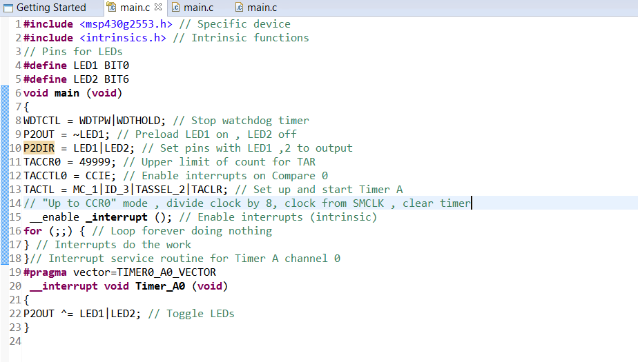
#include // Specific device #include // Intrinsic functions // Pins for LEDs #define LED1 BIT0 #define LED2 BIT6 void main (void) { WDTCTL = WDTPW|WDTHOLD; // Stop watchdog timer P2OUT = ~LED1; // Preload LED1 on , LED2 off P2DIR = LED1|LED2; // Set pins with LED1 ,2 to output TACCR0 = 49999; // Upper limit of count for TAR TACCTL0 = CCIE; // Enable interrupts on Compare 0 TACTL = MC_1|ID_3|TASSEL_2|TACLR; // Set up and start Timer A // "Up to CCR0" mode , divide clock by 8, clock from SMCLK , clear timer __enable _interrupt (); // Enable interrupts (intrinsic) for (;;) { // Loop forever doing nothing } // Interrupts do the work }// Interrupt service routine for Timer A channel 0 #pragma vector=TIMER0_A0_VECTOR __interrupt void Timer_A0 (void) { P2OUT ^= LED1|LED2; // Toggle LEDs } can any1 explain me this code..
  • 1. Please edit your post with the advanced editor and paste the code in using the  button so that it is readable.

    2. Be specific about what your question is. What don't you understand?

    Also, please try to use a descriptive subject for the post title when posting.

  • I APOLOGISE  FOR BEING VAUGE WITH MY STATEMENT...THE POST WAS'NT CLEAR EARLIER.MY QUESTION IS HOW DOES THE  CODE KNOW THAT AN INTERRUPT HAS BEEN GENERATED( IN THE ABOVE CODE).I AM ALWAYS CONFUSED WITH TACCR0,TACCTL0 AND TACTL.

    ALSO,HOW DO WE KNOW WHETHER AN INTERRUPT IS MASKABLE OR NMI WHILE  WRITING A  CODE?

    KINDLY HELP ME TO FIGURE IT OUT...

  • Sri,

    since you enabled the Capture Compare Interrupt in the TACCTL0 register, the timer module generates an interrupt when TAR hits the value set in TACCR0. TAR is a simple counter. You set it to MC_1, which means up-mode. So it counts from 0 to TACCR0 and then jumps back to 0, again starting to count up again. The jump-back needs one cycle, I guess you already know that and therefore set the TACCR0 value to 49999 instead of 50000. When hitting the CCR0 value, the interrupt is requested. Your timer runs from SMCLK and you have set ID_3, so the clock is divided by 8. SMCLK runs at about 1MHz in your case - you do not set any specific clock. So 1 MHz / 8 = 125 kHz. With CCR0 set to 49999 (+1), the interrupt will occur every 400ms.

    By the way - this line:

    P2OUT = ~LED1;

    is the same as

    P2OUT = ~(0000 0001);
    // is the same like
    P2OUT = 1111 1110;

    so LED1 is off, not on and LED2 is on, not off.

    Dennis

  • THANKS A TON DENNIS...IM GLAD U'VE MADE ME UNDERSTAND CODE AND THE MINUTE ERRORS AS WELL..
  • HI Sri,


    if an interrupt is maskable or non maskable you typically can find in the device individual datasheet. In case of the G2553 you can for example find the information in Table 5 on page 11 of the datasheet (SLAS734F):

    How to use interrupts is explained e.g. in the Family Users Guide. In case of the G2553 it's in section 2.2 of the 2XX Users (SLAU144J).

    In case of the Timer_A0 you can have multiple sources for the interrupt that all generate an interrupt on one interrupt vector. You can find out, what exactly triggered the interrupt by checking the TAIV register:

    Thanks and best regards,

    Christoph

  • Thank you Christoph..dat was really helpful.i have the datasheet but was unable to use it correctly.This has given me the direction .thanks again
  • Oh, I accidently read over that second question, sorry!

**Attention** This is a public forum