This thread has been locked.

If you have a related question, please click the "Ask a related question" button in the top right corner. The newly created question will be automatically linked to this question.

MSP432 What is the fastest way to trigger ADC14 after waking up from GPIO ISR from LPM3


Hi all,

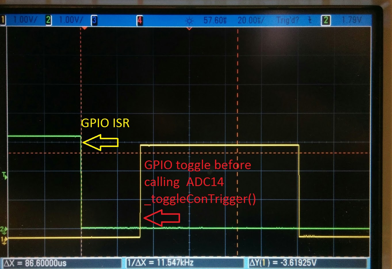
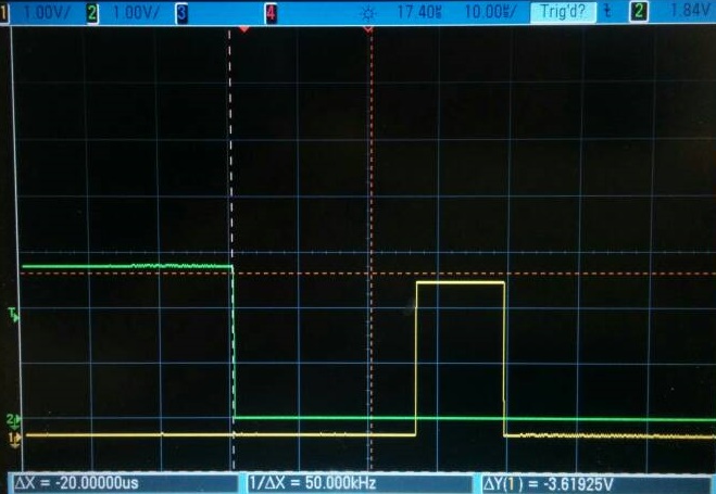
For my application, I need the MCU to trigger the ADC14 and sample as soon as it wakes up from LPM3 via GPIO ISR. I've set everything up before going to LPM3, but it seems like it will take at least 30us before anything is executed. Is there any faster way to trigger the ADC other then calling MAP_ADC14_toggleConversionTrigger(). Can I somehow tie the GPIO to trigger to the ADC trigger? Below is the relevant setup.

CS_setExternalClockSourceFrequency(32000,48000000);
//Clock is connected to PortJ.0~1
MAP_GPIO_setAsPeripheralModuleFunctionOutputPin(GPIO_PORT_PJ, GPIO_PIN0 | GPIO_PIN1, GPIO_PRIMARY_MODULE_FUNCTION);
MAP_CS_startLFXT(false);
MAP_CS_initClockSignal(CS_ACLK, CS_LFXTCLK_SELECT, CS_CLOCK_DIVIDER_1);
MAP_CS_initClockSignal(CS_BCLK, CS_LFXTCLK_SELECT, CS_CLOCK_DIVIDER_1);
PCM_setPowerState(PCM_AM_LDO_VCORE1);

    BITBAND_PERI(ADC14->rCTL0.r, ADC14ON_OFS) = 1;
    MAP_ADC14_configureConversionMemory(ADC_MEM0, ADC_VREFPOS_AVCC_VREFNEG_VSS,ADC_INPUT_A0, ADC_NONDIFFERENTIAL_INPUTS);
    MAP_ADC14_setResolution(ADC_8BIT);
    MAP_ADC14_initModule(ADC_CLOCKSOURCE_MCLK, ADC_PREDIVIDER_1, ADC_DIVIDER_4,0);
    MAP_GPIO_setAsPeripheralModuleFunctionInputPin(GPIO_PORT_P5, GPIO_PIN5, GPIO_TERTIARY_MODULE_FUNCTION);
    MAP_ADC14_configureSingleSampleMode(ADC_MEM0, false);
    MAP_ADC14_enableSampleTimer(ADC_MANUAL_ITERATION);
    MAP_ADC14_enableConversion();
    /* Going to LPM3 */
    while (1)
    {
        MAP_PCM_gotoLPM3();
    }
}

/* GPIO ISR */
void gpio_isr(void)
{
	MAP_GPIO_toggleOutputOnPin(GPIO_PORT_P2, GPIO_PIN2);//blue on
	uint32_t status;
        status = MAP_GPIO_getEnabledInterruptStatus(GPIO_PORT_P1);
        MAP_GPIO_clearInterruptFlag(GPIO_PORT_P1, status);

        if (MAP_ADC14_toggleConversionTrigger())
	{
    	      MAP_GPIO_toggleOutputOnPin(GPIO_PORT_P2, GPIO_PIN2);//blue off
	}
}

  • Hello Albert,

    As Table 6-27 of the device datasheet shows, an ADC conversion can be triggered by software or through a timer but not by a GPIO. There are a few microseconds lost to wake-up from LPM3 (Table 5-13 of the datasheet) and servicing the GPIO ISR, but to minimize time you can try directly writing the ADC14SC bit inside of the ADC14CTL0 register (ADC14CTL0 |= ADC14ENC | ADC14SC;) to avoid time lost due to servicing a sub function. This should be the very first thing done inside of the GPIO ISR to minimize the delay.

    Regards,
    Ryan
  • Thanks, Ryan. That's what I did earlier today. My code is now  simply

    void gpio_isr(void)

    {

    P2OUT |= 0x04;

    ADC14CTL0 |= ADC14ENC + ADC14SC;

    P2OUT &= ~0x04;

    }

    So assuming pin toggle requires ~5us, then the delay between LPM3 to first ADC sample is ~20us? 

    (I'm trying to catch structural vibration, the delay ultimately determines the size of my sensor)

  • That is a fair approximation, it looks like we are down to about 10 us expected latency and 10 more us to enter into the GPIO ISR.

    Regards,
    Ryan
  • Ryan,
    >ADC conversion can be triggered by software or through a timer
    Is it possible to trigger using msp432 timer in input capture mode which essentially would be triggering from GPIO?
  • Ilmars,

    That's a really creative idea, thank you for thinking outside of the box. Sadly the trigger sources are TAx_Cn signals which are internal to the device and not physically connected to any pins.

    Regards,
    Ryan
  • >Sadly the trigger sources are TAx_Cn signals which are internal to the device and not physically connected to any pins.
    Indeed. They are connected to corresponding CCR output unit. That's my point actually. Unfortunately documentation does not tell how output unit behave in CAP mode, you could explain that here - it's possible uses in CAP mode.
  • Ryan,

    Is there anyway to speed up the GPIO ISR? what if it was written in assembly?

    (Also, do you think TI has any plan on shortening the turn on? I just looked at 2 M3/4s from other manufactures, they are all around 2µs with 1µA sleep current)
  • Albert,

    Writing in assembly could speed up the GPIO ISR but most likely only by a few nanoseconds. Since the MSP432P401R is the first low-power M4-based MSP device it's likely that the turn-on time will be improved with future devices in the family.

    Regards,
    Ryan
  • Hey Albert,

    Below is some code I ran to test the response time from LPM3 wakeup. Changing the DCO frequency to 48MHz gives a response time of 7-8us. Lower DCO frequencies cause slower response times as expected.

    /* DriverLib Includes */
    #include "driverlib.h"

    /* Standard Includes */
    #include <stdint.h>

    #include <stdbool.h>

    int main(void)
    {
       volatile uint32_t ii;

       /* Halting the Watchdog */
       MAP_WDT_A_holdTimer();


       MAP_CS_setDCOFrequency(48000000);

       /* Configuring P2.5 */
       MAP_GPIO_setAsOutputPin(GPIO_PORT_P2, GPIO_PIN5);

       /* Configuring P2.4 as an input and enabling interrupts */
       MAP_GPIO_setAsInputPinWithPullUpResistor(GPIO_PORT_P2, GPIO_PIN4);
       MAP_GPIO_clearInterruptFlag(GPIO_PORT_P2, GPIO_PIN4);
       MAP_GPIO_enableInterrupt(GPIO_PORT_P2, GPIO_PIN4);
       MAP_Interrupt_enableInterrupt(INT_PORT2);

       /* Enabling SRAM Bank Retention */
       MAP_SysCtl_enableSRAMBankRetention(SYSCTL_SRAM_BANK1);

       /* Enabling MASTER interrupts */
       MAP_Interrupt_enableMaster();

       /* Going to LPM3 */
       while (1)
       {
       MAP_PCM_gotoLPM3();
       }
       }

    /* GPIO ISR */
    void gpio_isr(void)
    {

    uint32_t status;

    status = MAP_GPIO_getEnabledInterruptStatus(GPIO_PORT_P2);
    MAP_GPIO_clearInterruptFlag(GPIO_PORT_P2, status);

    /* Toggling the output on pin 2.5*/
    if(status & GPIO_PIN4)
    {
       MAP_GPIO_toggleOutputOnPin(GPIO_PORT_P2, GPIO_PIN5);
    }

    }

    (Blue is the GPIO interrupt, yellow is the ISR response)

    Regards,

    Martin

  • I think I got the similar result, but I think yours might be slightly faster. I will try again. In my code, I toggled a pin before and after ADC sample, and back solved for the ADC delay by subtracting the time it took to toggle. I think the totally delay from wakeup to sample was about 18us+, which is what I'm trying to minimize. (I had the ref set to VDD too)

**Attention** This is a public forum