- Ask a related questionWhat is a related question?A related question is a question created from another question. When the related question is created, it will be automatically linked to the original question.
Hello!
I've come across an example of generating 16-bit random numbers with the use of TimerA, ACLK and SMCLK. TI's wiki code for the MSP430 model is the following:
int TI_getRandomIntegerFromVLO(void)
{
unsigned int i;
int result = 0;
// setup Timer_A
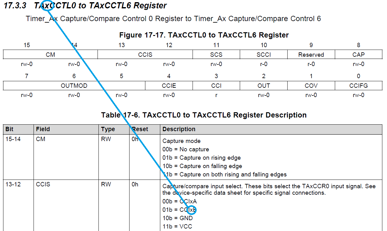
TA0CCTL1 = CM_1 + CCIS_1 + CAP;
TA0CTL |= TASSEL__SMCLK + MC__CONTINUOUS;
for(i=0 ; i<16 ; i++)
{
// shift left result
result <<= 1;
// wait until Capture flag is set
while(!(TA0CCTL1 & CCIFG));
// clear flag
TA0CCTL1 &= ~CCIFG;
// check LSB
if(TA0CCR1 & 0x01)
{
result |= 0x01;
}
// change the divison of timer input clock
TA0CTL = (TA0CTL & 0xFCFF) | ((TA0CCR1 & 0x03) << 8);
}
return result;
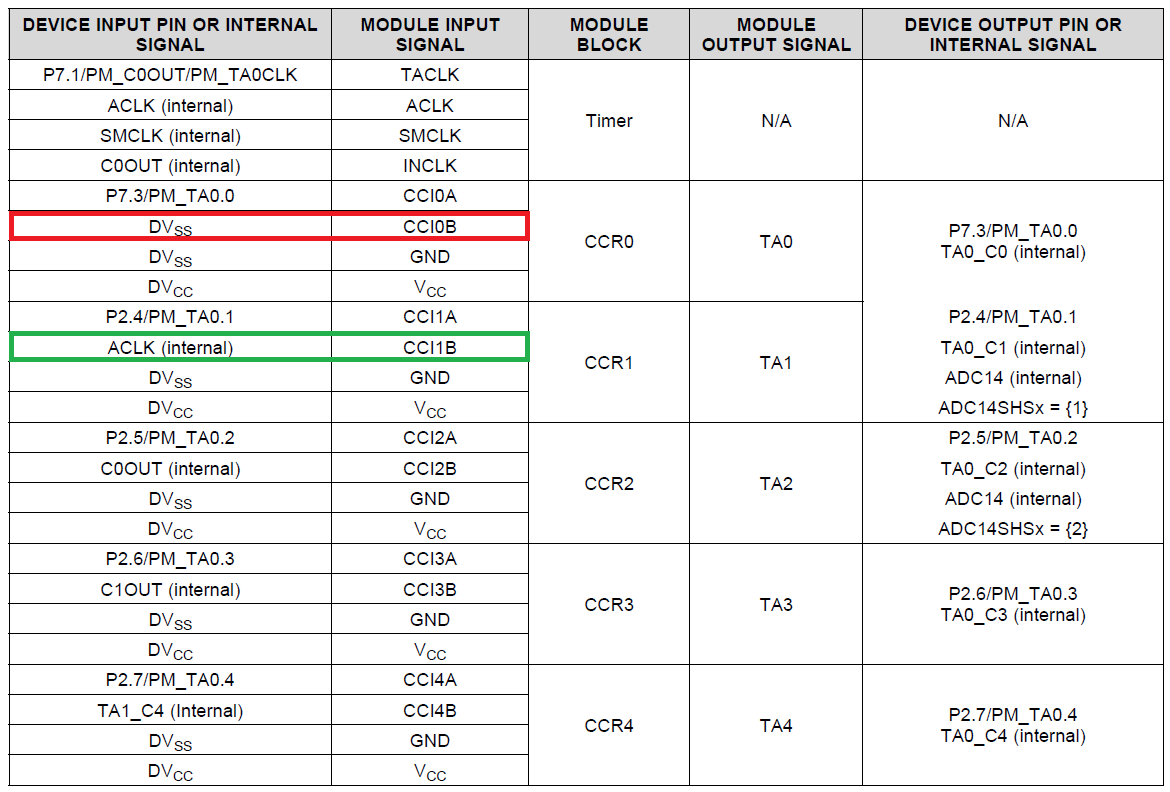
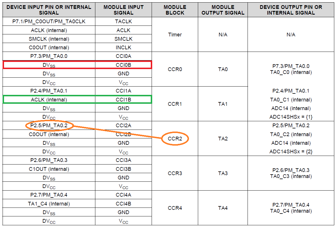
}It is simple enough and I tried recreating it for MSP432 in Code Composer 6.1, but with no luck so far. Register addresses remain the same if I'm doing this correctly (TA0CCTL1 can get internal ACLK as input via CCIS_1 on both boards), but somehow it gets stuck at the "while(!(TA0CCTL1 & CCIFG));", never moving forward. The only thing I added is the line to set VLO as a source for ACLK:
CSCTL1 = (CSCTL1 & ~(SELA_M | DIVA_M)) | SELA_1;
Does anyone have any idea? Any help would be greatly appreciated.


**Attention** This is a public forum