This thread has been locked.

If you have a related question, please click the "Ask a related question" button in the top right corner. The newly created question will be automatically linked to this question.

MSP432 Interrupt Vector Handler


Hello,

The interrupt vector handler definition for MSP430 can, according to the internet, be written as:

#pragma vector=TIMER0_A0_VECTOR
__interrupt void Timer0_A0(void)
{
	//do something
}

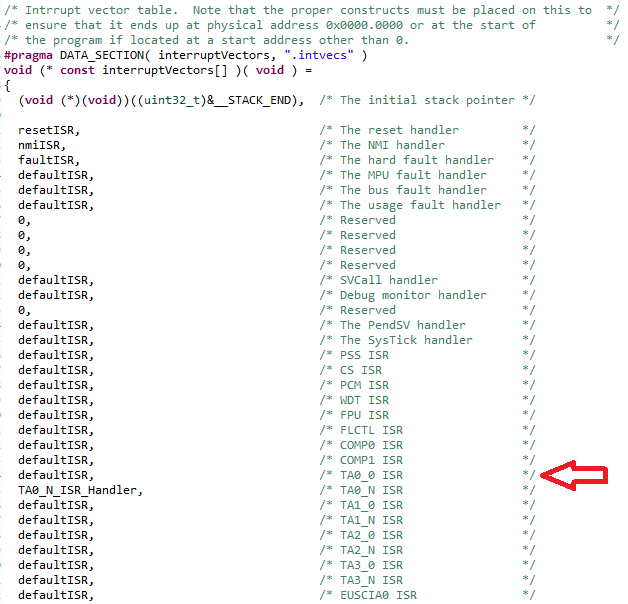
What would be an equivalent for MSP432? In msp432.h I've found some definitions for Timer Interrupt vectors in form of TAxIV, is this a replacement for TIMER_A0_VECTOR?

If I run the modified code (TAxIV instead of TIMER_A0_VECTOR), CCS 6.1, compiler version TI 5.2.5, reports a serious compiler problem (segmentation error), so this is clearly not the case. 

I've also found some examples of interrupts for MSP432, which use __enable_interrupt(), but I can't piece it all together, because I can't find any examples which demonstrate the whole thing and I'm still kind of new to everything.

Thanks in advance!

  • Jimmy,

    look at the "MSP432 Platform Porting Guide" which can be downloaded here. Chapter 4.2.3 describes the interrupt system.

    There are two interrupt vectors for the TimerA:

    • TAxCCR0 interrupt vector for TAxCCR0 CCIFG
    • TAxIV interrupt vector for all other CCIFGs and the TAIFG

    You still have to write an interrupt function for CCR0 and/or CCR1,2,3,... The CCR0 function has a dedicated one and it's flag is cleared when entering the ISR. CCR1,2,3,... and TAIFG share one interrupt function. You can use the TAxIV inside this function to determine the highest pending flag. When accessing TAxIV, this highest pending flag is automatically reset. But this is similar to the MSP430 IV working principle.

    For the MSP432 you typically use the startup file to place the name of your specific ISR for the module into the table and you then enable the interrupt in the NVIC module. Your ISR can have any name you want, but it has to be declared in the startup file.

    Dennis

  • Thanks for the fast reply. Ok, so if I'm understanding this correctly, NVIC is a vector table which stores interrupts based on their priorities. Would the following line

    NVIC_ISER0 = 1 << ((INT_TA0_0 - 16) & 31);

    store a TimerA0 interrupt in the table at some position, to get accessed as soon as all the reserved interrupts are ignored?

    And for the silliest question: I see interrupt handlers declared as void functions outside main(), but they're never called inside main(), so how would this work? I compile and run the program from the link below on CCS without a problem, but it doesn't seem to work at all, even with the correction suggested one post below:

    e2e.ti.com/.../432089

  • From the header file (and the datasheet) you get

    #define INT_TA0_0 (24) /* TA0_0 IRQ */

    so setting

    NVIC_ISER0 = 1 << ((INT_TA0_0 - 16) & 31);

    is correct because 24 - 16 = 8 which is <= 31 and is therefore set in ISER0. If it was greater, like INT_PORT1 (51), then it would be 51 - 16 = 35 and this would be ISER1 because ISER0 only reaches to 31 as it is a 32 bit register. Note that setting one bit can be done with "=" in this case. Normally this expression would clear other set bits, but NVIC_ISERx can only set bits, but not clear them, so it doesn't make a difference whether you use "|=" or "=". For clearing bits you use NVIC_ICERx.

    Jimmy Wein said:
    store a TimerA0 interrupt in the table at some position

    You have to open the startup file for your project - it is located in the project explorer. There you have this table:

    This is from one of my projects now, so I have a function for TA0_N - you would have to place one for TA0_0. Chose any name you want here. As a second step you have to declare this function here (also the startup file):

    Again, this is from my project, so just place your new function name in here, but don't forget extern void functionname( void );

    Jimmy Wein said:
    And for the silliest question

    There are no silly questions

    Jimmy Wein said:
    interrupt handlers declared as void functions outside main(), but they're never called inside main(), so how would this work?

    The interrupt calls this function that is why you place your function's name for the appropriate interrupt in the table of the startup file. When the interrupt 24 is now invoked, the program jumps to your manually set function. And because it is listed in the table the program knows where to jump to. You simply place your function somewhere in your code files, under the main, for example:

    Different to the MSP430, but quite easy anyway if you once did it.

    Dennis

  • Thanks a great bunch Dennis, I'm going to chew through this now :) Going to report back once I get something working!
  • You are also welcome to report back if it is not working :)
  • Okay, I tried out an example I mentioned above and it's working now. I also implemented the frequency counter originally written for MSP430, just needed to change the timer registers and interrupt handlers for two timers. I think I get the general idea now, thanks again!
  • You're welcome! Have fun!
  • Okay, so as expected I ran into some problems :D. Basically, when I call the function containing the timers for frequency measurement, MSP432 freezes. It doesn't always happen, but it happens eventually in debug mode. When I compile in release mode, it happens the first time the function is called.

    I'm using two timers to measure the frequency of internal or external signal. I initialize the timers with 

     __enable_interrupt();
    NVIC_ISER0 = 1 << ((INT_TA0_0 - 16) & 31); //enable TA0_0 interrupt
    NVIC_ISER0 = 1 << ((INT_TA1_N - 16) & 31); //enable TA1_1 interrupt
    
    
    TA0CCR0 = 20000;			// 20000 * 2400 = 48 MHz operation
    TA0CCTL0 |= CCIE;
    TA0CTL |= TASSEL_2;
    
    TA1CCTL1 |= CCIS_1 + CM_2 + CAP + CCIE;
    TA1CTL |= TASSEL_2;

    The interrupt handler function declaration:

    void TimerA0_ISR (void)
    {
    	counter++;
    	TA0CCTL0 &= ~CCIFG;
    }
    
    void TimerA1N_ISR (void)
    {
    	freq++;
    	TA1CCTL1 &= ~CCIFG;
    }

    The frequency measuring code itself:

    void print_frek(void){
    
    	TA0CTL |= MC_1;				//start the timers
    	TA1CTL |= MC_1;
    
    	while(counter != 2406);	//fine tune this number for accurate frequency results, around 2400 for 48 MHz DCO
    
    
    	TA0CTL &= ~MC_0;				// stop timer
    	TA1CTL &= ~MC_0;				// stop timer
    	result = freq;
    	printf("Frequency: %d\n", result);      //for debugging purposes
    	counter = 0;			                        // reset counter
    	freq = 0;			                                // reset freq. count
    	TA0R = 0;				        	// reset timerA0 register
    	TA1R = 0;					        // reset timerA1 register
    
    }

    For testing purposes I'm using this in a dirty button-push loop like this:

    	while(1)
    	{
    		printf("standby!\n");
    		if(~P1IN & BIT1){
    		print_frek();
    		}
    	}

    This works for a first dozen or so calls of the print_frek() function, where it correctly displays the internal ACLK frequency, but sooner or later, it freezes. If I'm not using any loops or button pushes, it works indefinitely.  Any ideas? At first I thought It had something to do with DCO frequencies, but the behaviour is the same at every HF setting. The VCORE level is also at 1. Thanks! 


  • Jimmy, first thing I see is the following:

    TA0CTL &= ~MC_0; // stop timer
    TA1CTL &= ~MC_0; // stop timer

    MC_0 is 0x0000, so when writing ~MC_0 you write 0xFFFF. This leads to an unchanged TAxCTL because you &= all the register's bits with 1. Your register stays completely unchanged in that case. You want to do

    TA0CTL &= ~MC_3; // stop timer
    TA1CTL &= ~MC_3; // stop timer

    to clear both bits of the MC.

    Dennis

  • Again, that's the solution! Thanks a lot. I'm surprised it even worked as it was, I just read the descriptions next to the values in "msp432.h" and set the corresponding bits (in the wrong way!).
  • Glad it works now :)
  • One more question, does TimerA run independently of CPU, meaning CPU can do other stuff while the timer is counting?
  • The TAxR registers are sourced from the clock source you specified for them. But they are connected in hardware. With setting the individual bits you simply route the selected clock source to the timer module and by the divider bits, for example, you route the clock signal through some flip-flops (or grab the signal from another flipflop, I don't know the internal construction), but it is all done in hardware.

    Example for a clock-divider:

    (Just a pic from the net - f/16 is not a divider from the timer A module)

    So in short: The timer is sourced without interaction of the CPU. The timer can ping the CPU in form of an interrupt to react on a special event. The CPU can even be in low power mode and the timer is still running, waking the CPU up to do something.

    Dennis

  • Okay, thanks. So in theory, it would be possible to generate pulses with MSP and have a frequency counter to measure frequency of said pulses without interfering with pulse generation too much?
  • I don't know your pulses and the amount of CPU processing they require, but the timer could, for example, generate output pulses like a PWM or a square wave without any CPU interaction. For a frequency counter, the timer also runs without the CPU, collecting the incoming pulses, but for processing the result when the timer generates an interrupt, the CPU must jump in, of course.
  • Okay, thanks, that's what I wanted to know :) .

**Attention** This is a public forum