This thread has been locked.

If you have a related question, please click the "Ask a related question" button in the top right corner. The newly created question will be automatically linked to this question.

Difference PMMSWBOR and H/W reset on MS430F6xxx

Expert 2355 points

Hi,


I try to reset by software with PMMSWBOR.

But,I dont know H/W and S/W reset is same or not.

What is different PMMSWBOR from H/W reset?
Is the signal path of PMMSWBOR same as H/W reset when reset signal receved as Figure 1-1. BOR/POR/PUC Reset Circuit?

best regards,

kyt

  • The five different BOR sources will result in different values in the SYSRSTIV register, but otherwise are handled in the same way.
  • Thank you for your reply.

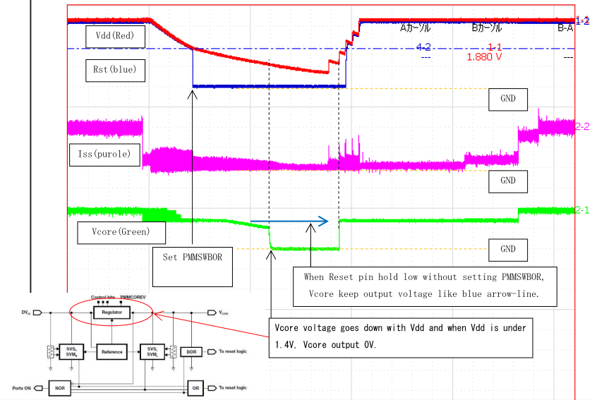
    I focused Vcore Voltage.

    If PMMSWBOR was set, Vcore voltage go down when VCC is under 1.4V.

    But reset-pin hold low(H/W reset), Vcore voltage continue output when VCC is under 1.4V.

    This image is setting PMMSWBOR wave form.

    Is  it correct operation?

  • Hi kyt,

    I'm trying to better understand how you are using the PMM in this case. Can you provide some more information:
    1. PMMSWBOR can only be set by your code. Therefore I was wondering when you are setting this bit? I see in your diagram above, it looks like you set PMMSWBOR after Vcc has fallen a certain amount? Are you configuring the SVS somehow to give you an interrupt, and in that ISR just setting PMMSWBOR? Or are you actually not setting PMMSWBOR and are letting the SVS directly trigger a reset? Just trying to understand how you are using the reset and your situation.
    2. How is your SVS configured? Are you using driverlib for setting the Vcore level? CAn you provide us a code snippet or simplified code example and instructions on how to run the same test on one of our TI target boards, so that we can see the same behavior and better understand what you are asking?
    3. Which MSP430F6xx device are you using? I'm asking because some devices have battery backup module (with a VBAT pin) and others have an AUX module and these can also interact with the different types of resets.

    Regards,
    Katie
  • I also asked about the difference between PMMSWBOR and pulling the RST line, and the answer I got was this:
    "If there is only a short pulse on the RST line there shouldn't be any difference on how the device reacts - with one exception: different IFGs are set and different SYSRSTIV values are generated. "

    They went on to say that they think that the difference you are observing is because you keep the RST line low for an extended period of time. Setting the SWBOR just generates a short reset pulse and it is not possible to keep the device in reset for an extended period of time using the software bit SWBOR.

    Regards,
    Katie
  •  

    Katie-san


    Thank you for your respond.

    I'm appreciate for your reply.


    1.SW BOR bit is set in NMI_ISR in my application code.

    2.SVS setting is default.

    3.Target device:MSP430F67xx(Null)


    Reset pulse is not short.


    Our simple test code is as below:

    Note: this code is not our application code

    #include <msp430.h>


    void main(void)

    {

        WDTCTL = WDTPW | WDTHOLD;               // Stop WDT


        // Setup P5.3 output, P1.5 SMCLK, P1.4 MCLK, P1.2 ACLK

        P1DIR |= BIT0;                          // Set P5.3 to output direction

        P1OUT &= ~BIT0;                         // Clear P5.3

        P1DIR |= BIT2 | BIT4 | BIT5;            // ACLK, MCLK, SMCLK set out to pins

        P1SEL0 |= BIT2 | BIT4 | BIT5;            // P1.2,4,5 for debugging purposes.


        while (1)

        {

            P1OUT |= BIT0;                      // Toggle P5.3

            __delay_cycles(600);              // Delay

            P1OUT &= ~BIT0;

            PMMCTL0 |= PMMPW + PMMSWBOR;

        }

    }


    Also, I have one question.

    In below situation of holding reset status(not release), is there any difference of internal LDO?

    SVS is same register setting.

    VCC goes down 0V from 1.8V, Vcore voltage go 0V.

    And VCC is difference case 1) nad 2).

    Case1)Hard ware reset:pull down RST-pin to low level

    When VCC =1.10V, Vcore goes 0V.

    Case2)Software reset:set PMMSWPOR with password

    When VCC= 1.48V, Vcore goes 0V.


    The reset factor seems influence.

    Is it correct operation or not?


    kyt

  • Hi kyt,

    I still do not understand your graphs from before - were you also having Vcc go low during the reset? How is the MSP supplied? It doesn't look like you have a stable supply voltage during the test - are you intentionally having the supply drop as part of the test?

    Regards,
    Katie
  • This discussion is continuing offline.

**Attention** This is a public forum