This thread has been locked.

If you have a related question, please click the "Ask a related question" button in the top right corner. The newly created question will be automatically linked to this question.

MSP430 CPU OFF in IAR systems compiler

Other Parts Discussed in Thread: MSP430F5438A, MSP430FR6889

Hi,

I am using 'MSP430F5438A' micro controller , I am facing an issue in recent times though it is used from past 3 years. 

Back Ground of Application: On Switch Press ,12v supply has to be enabled to the other boards connected to it.

Issue : In recent times observed a Reset of micro controller by External Watch Dog, where refresh of External watch dog performed in while(1).

In the debugging identified 2 Behaviors.

1.After Switch Press, Main while(1) is not getting executed, but interrupts are getting served. SYSNMI interrupt are getting triggered infinitely. Also observed that  when SYSNMI is triggered 'VMAIFG' Flag is set.

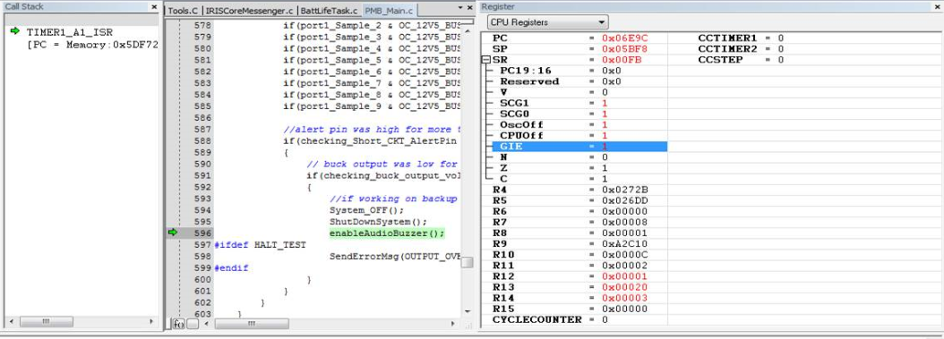
2.Other behavior is after switch press,if i try to keep break points getting a warning:CPU is OFF and Further debugging is not possible then i  checked CPU Register status CPU OFF,OSC OFF,SCG0,SCG1 bits are set.

Needed help in  understanding the reason to cause this behavior.

Thanks in Advance.

Regards,

venkatesh

  • Hi Venkatesh,

    So the same hardware & software has been used for the past 3 years but only now is the issue being noticed? Has anything been changed during this time? Do you notice any strange behavior by the Vcc rail once the switch is pressed? And the external watch dog is only serviced in the while(1) active state of the MSP430?

    The two behaviors you note (main code not executing and CPUOFF = OSCOFF = SCG0 = SCG1 = 1) indicate that the device has entered a low power mode. This explains why the CPU is off, debugging is not possible, and the while(1) is not being serviced while interrupts are. Do you ever intentionally enter a low power mode (LPM) with global interrupts enabled (GIE)? Can you locate the point at which the CPU register status bits are set? Finding this in your code will help solve the issue.

    Regards,
    Ryan
  • Hi Ryan,

    Answer to your questions , Software is same but Hardware has under gone for layout change.Issue is consistently reproducible only in one Board . External Watch Dog is only refreshed in while(1).Software is not intended to enter to Low Power Mode(LPM).GIE bit is set before While(1) , No other CPU Status Register (SR) bits are set anywhere in the code. VCC rail is also Good.

    Regards,
    Venkatesh

  • Hello Venkatesh,

    Only one board in how many units? Have you been able to reproduce the issue, if only once, on any other devices? Do you re-flash the device or go straight to debug mode? Are you using SBW or JTAG for communication? The CPU register status bits should never be set if not intending to enter a LPM so this is strange behavior. Are these bits already set on device start-up? I would most definitely like to locate where the CPU register status bits are set.

    Regards,
    Ryan
  • Hi Ryan,

    We kept for Long Run test of 5 units of same type,in that reset observed once in one unit.Then observed occurrence of this intermittently in other units also but issue is consistently reproducible in 1 unit even if re flashed.I re flashed through JTAG in debug mode and if i tries to debug  line by line, issue is not reproducible.Even in debug mode with out break point issue is reproducible.

    We are not using any library startup functions,No where in the code called __intrinsic int __low_level_init(void);

    Before switch press if i check the status register ,LPM bits are not set.After switch press only LPM bits are set.  

  • Hi Venkatesh,

    Please explain this to me again, was this issue present on previous hardware revisions? Would it be possible for you to provide a design schematic and possibly highlight recent revision changes? Am I also to assume that you are using the RST/NMI pin for NMI functionality and are prepared for a UNMI ISR? Are you sure that pressing the switch does not cause a device reset? Is the "switch" in question an actual switch or push button, and is there any code or logic centered around its operation? What is inside the System_OFF() and ShutDownSystem() subfunctions? I apologize for all of the questions as I try to debug this problem.

    Regards,
    Ryan
  • HI Ryan,

    In brief, this board (MSP430 is uC) is a power management Board which has Power supply connection ,this allow Power supply to subsystems based on switch press. This switch is connected to IO pin of uC. If this switch is pressed more than 300msec ,software detects the switch Press and Enables the supply to subsystem boards.Issue is when this switch is pressed(connected to uC IO) Power getting enabled to Subsystems but Power management Board is getting hanged and resetting by External watch dog.

    Now to answer questions, This issue is not preset in previous hardware versions.I can share schematics to your TI email ID,Please share your mail ID.

    RST/NMI pin used to RESET , UNMI ISR configured.

    Switch is connected to uC IO pin.Pressing a switch is not causing any uC RESET,but software main while loop is not executing.because of it Extenal WDT resets uC.

    When switch press detects by software,software Sets other uC IO pin to HIGH, hardware logic takes care to enable supply when this pin is set HIGH.

    System_OFF() and ShutDownSystem() functions are having logic to Turn OFF supply to subsystems.Its a safety Logic to turn OFF supply to subsystems.


    Regards,
    venkatesh

  • Hi Venkatesh,

    I've sent you an E2E friend request, please accept it so that we can start a private conversation.

    I have some slight confusion regarding the RST/NMI pin. You say that it is used in RESET mode but a UNMI interrupt is generated by an edge on the RST/NMI pin when configured in NMI mode. Either that or you are using it for when an oscillator fault occurs, perhaps this will become more clear once I see the schematics.

    Regards,
    Ryan
  • This issue was closed offline, the root cause being a hardware issue. More details will be provided if they become available.

    Regards,
    Ryan
  • Hi ,

    I came to this thread, As it's about similar to my issue, That is why I am responding in here.

    I have my project flow as below,

    -- I have sensors on i2c that I have to read on every 1ms
    -- have to collect data and send over uart via dma
    -- Responding on request on particular sensors data.
    -- serve int if any comes from sensors,

    I am facing situation is that, I observe with debugging, That In most cases, the program counter ran in to area of 0xFFFA .
    I have checked in linker file , the address allocated to the INT. and I have checked that INT and I came to know it's UNMI int.
    So on that Address I am getting UNMI Interrupt.

    So What might be the reason for this, And How to recover.?

    If you need more data or specifics, I would like to give, And some I cannot Share here. But Wanted to solve this issue.

    Thanks,

  • Hinesh,

    A UNMI interrupt can be generated by the following sources:

    NMIIFG: An edge on the RST/NMI pin when configured in NMI mode
    OFIFG: An oscillator fault occurs
    ACCVIFG: An access violation to the flash memory

    Can you determine which of these causes the interrupt? No information you have provided so far indicates that this issue is similar to the original thread. Has a change in hardware or software caused the failure? Are you able to return to a working condition and figure out what change causes the problem?

    Regards,
    Ryan
  • Hi ,

    Yes When I read in data sheet it's says same. But How to check for the source.

    I have took break point and checked register at that time and the clock LFXT was set as 1 though I have not used it in my program.
    And when I tried to Reset it's value It was set as 1 only.

    -- There are not NMI /RST is generated from my program nor externally.
    -- The whole project runs smooth for dma transfer as well as 1ms read from I2C, But When req. is done for any sensor data it runs for 2-3 times after that it goes in to 0xFFFA address, that's UNMI.

    -- I have Re-change in hardware and issue was same. and in software. There is no change is there.
    -- And I am using my controller on 8mhz internal clock ( Controller is MSP430FR6889) SO there is not access violation as per the FRAM State.

    --

  • Check the IFG flags in the register window of your debugger to determine the interrupt source. Are you saying that the OFIFG is set even though you have not initialized or used the LFXT in your program? Do you have an external crystal connected to the XT pins? Is OFIFG not set before the sensor data request and set afterwards? Do any of the sensors use a peripheral that is sourced by a clock sourced by the LFXT? Is there any possibility of ISR overlap, for example between the DMA/I2C and the sensor peripherals?

    Regards,
    Ryan
  •  Hi ,

    -- I have provision of external crystal but I am not using anywhere. I am just working on SMCLK ( 8mhz)
    -- I am not able to detect the possibility of overlapping of ISR, but I am using DMAIE and I2C interrupts for sensors.
    -- I have disabled the external interrupts coming from sensors. for now.
    -- Yes I have observed that in CCTL4 Register I Saw that LFXT value remains 1 though, If I try to make it 0.
    -- I have not used LFXT as source in my code anywhere.
    -- LFXT flag was not set when the 1ms i2c read is going on ( as individual It's running fine)
    -- But when Request for data (1ms I2C read will also be On at that time ) first 2-3( random) times it comes perfect.
    -- When not come, I pause the program in ccs and its says the at location 0xFFFA.

     if you need the code to check, I can mail or share you the code so that you can share light on it. I have also attached the screen-shot of my problem.

    I have got one more screen shot of what you have said. Please find it below.


    Thanks.,

  • Hinesh,

    You have disabled the sensor external interrupts and yet the problem persists, just using the DMA and I2C? Even if you are not using it, make sure you initialize the LFXT properly (including an oscillator fault flag check loop) if an external crystal is connected. I don't know what you mean by the CCTL4 register, you should be checking SFRIFG1 for the OFIFG.

    Regards,
    Ryan
  •  Hi Ryan Brown1 (3460875) ,

    I have done the check and attaching the snap shot.

  • Hi ,

    Is there any updates for the above Issue.? Is there any more information you required for this?
    Please ask,
    Thanks,
  • Hi Hinesh,

    You have confirmed that you are looking at the correct register but you have not provided any additional feedback since my latest inquiry, therefore I do not have any more comments to provide. You need to handle the crystal setup properly inside of your code to avoid the OFIFG and respective UNMI.

    Regards,
    Ryan
  • Hi Ryan Brown1 (3460875) ,

    Please check my previous reply., In that I have took a screen shot of registers when the fault occurs,. And it was replied  on Mar 2, 2016 7:17 PM .

    Please check the post, I have given the information you have asked for.

    Moreover I am pasting my clock configuration for the 8mhz that I have did in my code.

           CSCTL0_H = CSKEY >> 8;               /* Unlock CS registers */

    CSCTL1 = DCOFSEL_6;                  /*  Set DCO to 8MHz */

    CSCTL2 = SELA__VLOCLK | SELS__DCOCLK | SELM__DCOCLK;  /* Set SMCLK = MCLK = DCO */

    CSCTL3 = DIVA__1 | DIVS__1 | DIVM__1;     /* Set all dividers to 1 */

    CSCTL0_H = 0;                             /* Lock CS registers */

    And Also I am using uart at baud rate 460800 and for that clock register configuration are as below.

           UCA0BR0 =17;

          UCA0MCTLW |= 0x4A00;

    I am using I2C at 400khz and for that the clock configuration is as below. (I am using 2 I2C and for both clock setting is same.)

          UCB0CTL1 = UCSSEL__SMCLK + UCSWRST;  /* Use SMCLK, keep SW reset */

    UCB0BR0 = 20;  /* I2C clock = SMCLK value = 400KHz */

    UCB0BR1 = 0;

    If There is any thing wrong in clock setting register, You can tell me., Will correct. And also Pasting my screenshot of register (from CCS) when the fault occurs.

  • Hinesh Gohel said:
    I am facing situation is that, I observe with debugging, That In most cases, the program counter ran in to area of 0xFFFA .
    I have checked in linker file , the address allocated to the INT. and I have checked that INT and I came to know it's UNMI int.
    So on that Address I am getting UNMI Interrupt.

    What do you mean "ran in to area of 0xFFFA"?

    What is the content of the address 0xFFFA? Please show us all the contents of addresses from 0xFFD0 to 0xFFFF.

    I do not think your problem is caused by a UNMI. Because that would cause the PC to be loaded with the content of 0xFFFA which is probably not in "the area of 0xFFFA". 

  • Hi old_cow_yellow.,

    1. ) In the area 0xFFFA ( as per linker file ) "INT53", and
    UNMI : { * ( .int53 ) } > INT53 type = VECT_INIT .

    2.) So as per the data sheet I have checked it's UNMI. And I have not modified the INT locations in linker file.

    3.) the contents of address from 0xFFD0 to 0xFFFF Are as below.

    INT32 : origin = 0xFFD0, length = 0x0002
    INT33 : origin = 0xFFD2, length = 0x0002
    INT34 : origin = 0xFFD4, length = 0x0002
    INT35 : origin = 0xFFD6, length = 0x0002
    INT36 : origin = 0xFFD8, length = 0x0002
    INT37 : origin = 0xFFDA, length = 0x0002
    INT38 : origin = 0xFFDC, length = 0x0002
    INT39 : origin = 0xFFDE, length = 0x0002
    INT40 : origin = 0xFFE0, length = 0x0002
    INT41 : origin = 0xFFE2, length = 0x0002
    INT42 : origin = 0xFFE4, length = 0x0002
    INT43 : origin = 0xFFE6, length = 0x0002
    INT44 : origin = 0xFFE8, length = 0x0002
    INT45 : origin = 0xFFEA, length = 0x0002
    INT46 : origin = 0xFFEC, length = 0x0002
    INT47 : origin = 0xFFEE, length = 0x0002
    INT48 : origin = 0xFFF0, length = 0x0002
    INT49 : origin = 0xFFF2, length = 0x0002
    INT50 : origin = 0xFFF4, length = 0x0002
    INT51 : origin = 0xFFF6, length = 0x0002
    INT52 : origin = 0xFFF8, length = 0x0002
    INT53 : origin = 0xFFFA, length = 0x0002
    INT54 : origin = 0xFFFC, length = 0x0002
    RESET : origin = 0xFFFE, length = 0x0002
  • What you have shown is the Map. I meant something like this:

  • ok., I am using CCS. do you know how I can show you this in CCS?
    If yes, Than I can directly check.

    And If I am not mistaken You are asking something like below?

  • Okay.

    It looks like all the unused interrupts share the same trap at location 0xCF42 which is probably a do nothing infinity loop. If the Program Counter ended there, you really cannot tell which one of the unused interrupt caused it. I cannot rule our UNMI, but there is no evidence that it is the cause of the problem. It is possible that the problem is not related to interrupt at all.

    I cannot say you are barking at the wrong tree, but there are a whole forest of other trees.
  • so what you suggest, I ended up in this forest only and how do i get out. I mean what precaution I need to take.

**Attention** This is a public forum