This thread has been locked.

If you have a related question, please click the "Ask a related question" button in the top right corner. The newly created question will be automatically linked to this question.

Configuring the clock for spi

Other Parts Discussed in Thread: MSP430FR5972

Hi , I am using msp430fr5972 , i have configured the clock .

 CSCTL0_H = ( CSKEY >> 8);                    // Unlock CS registers cskey is 0XA500
         CSCTL1 = (0x0006);                       // Set DCO to 8MHz
         CSCTL2 = SELA__VLOCLK | SELS__DCOCLK | SELM__DCOCLK;  // Set SMCLK = MCLK = DCO
                                                   // ACLK = VLOCLK
         CSCTL3 = DIVA__1 | DIVS__1 | DIVM__1;     // Set all dividers to 1
         CSCTL0_H = 0;                             // Lock CS registers

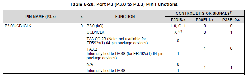
 and configuring port3 to primary function for spi . like this

P3SEL0 &= ~ BIT0;
    P3DIR |= BIT0;
    P3OUT |= BIT0;             //Make SCLK High

but i am unable to see the clock on my port on oscillator . Can any one help me how to configure a clock for spi in my msp430fr5972 .

Regards

Mohammed Shahrukh khan

  • Hi Mohammed!

    When you want to use the SPI function, you have to set the pins to that special function first. P3.0 is UCB1CLK, you already noticed that. But look at the datasheet, page 81:

    The table shows that you have to set P3SEL0 for UCB1CLK. You cleared this bit. Furthermore P3DIR and P3OUT are don't care because the pin is controlled by the USCI module in that case.

    Then you did not configure the USCI module. Look at the code examples to see how this is done. You can download them on the product website for the controller.

    And you maybe misunderstood the function of the pin. It will not continuously output a clock signal - it only outputs a clock signal when a transmission is active. When something is placed into the TX buffer it will start to output a clock signal. But only if the USCI mnodule is configured properly.

    Dennis

  • Thanks Dennis i will correct this out .
  • Hi Dennis Still i am unable to do . I am doing like this .

    P3SEL1 &= ~BIT0;
    P3SEL0 |= BIT0;
    P3SEL1 |= BIT4 | BIT5 | BIT6;
    PJSEL0 |= BIT6 | BIT7; // For XT1

    // Disable the GPIO power-on default high-impedance mode to activate
    // previously configured port settings
    PM5CTL0 &= ~LOCKLPM5;

    // XT1 Setup
    CSCTL0_H = CSKEY >> 8; // Unlock CS registers
    CSCTL1 = DCOFSEL_0; // Set DCO to 1MHz
    CSCTL2 = SELA__LFXTCLK | SELS__DCOCLK | SELM__DCOCLK;
    CSCTL3 = DIVA__1 | DIVS__1 | DIVM__1; // set all dividers
    // CSCTL4 &= ~LFXTOFF;
    // do
    // {
    // CSCTL5 &= ~LFXTOFFG; // Clear XT1 fault flag
    // SFRIFG1 &= ~OFIFG;
    // }while (SFRIFG1&OFIFG); // Test oscillator fault flag
    CSCTL0_H = 0; // Lock CS registers

    // Configure USCI_A0 for SPI operation
    UCA0CTLW0 = UCSWRST; // **Put state machine in reset**
    UCA0CTLW0 |= UCMST | UCSYNC | UCCKPL | UCMSB; // 3-pin, 8-bit SPI master
    // Clock polarity high, MSB
    UCA0CTLW0 |= UCSSEL__ACLK; // ACLK
    UCA0BR0 = 0x02; // /2
    UCA0BR1 = 0; //
    UCA0MCTLW = 0; // No modulation
    UCA0CTLW0 &= ~UCSWRST; // **Initialize USCI state machine**
    UCA0IE |= UCRXIE; // Enable USCI_A0 RX interrupt
    TXData = 0x1; // Holds TX data

    while(1)
    {
    UCA0IE |= UCTXIE;
    __bis_SR_register(LPM0_bits | GIE); // CPU off, enable interrupts
    __delay_cycles(2000); // Delay before next transmission
    TXData++; // Increment transmit data
    }
    return 0;
    }

    #if defined(__TI_COMPILER_VERSION__) || defined(__IAR_SYSTEMS_ICC__)
    #pragma vector=USCI_A0_VECTOR
    __interrupt void USCI_A0_ISR(void)
    #elif defined(__GNUC__)
    void __attribute__ ((interrupt(USCI_A0_VECTOR))) USCI_A0_ISR (void)
    #else
    #error Compiler not supported!
    #endif
    {
    switch(__even_in_range(UCA0IV, USCI_SPI_UCTXIFG))
    {
    case USCI_NONE: break;
    case USCI_SPI_UCRXIFG:
    RXData = UCA0RXBUF;
    printf("Rx data :%s \n",RXData);
    UCA0IFG &= ~UCRXIFG;
    __bic_SR_register_on_exit(LPM0_bits); // Wake up to setup next TX
    break;
    case USCI_SPI_UCTXIFG:
    UCA0TXBUF = TXData; // Transmit characters
    UCA0IE &= ~UCTXIE;
    printf("Tx data :%s \n",TXData);
    break;
    default: break;
    }
    }
    My hfxin and hfxout is connected to pj.6 and pj.7 . and my UCA1SIMO UCA1SOMI UCA1CLK IS CONNECTED TO P3.4 P3.5 P3.6 . Still i am unable to get . plzz help
  • You can output your clock signal via special functions SMCLK and MCLK. First check if the clock signal is working well.

**Attention** This is a public forum