For the Loop Back Test I came to the following code. I still have not got it to work!
#include "msp430f47197.h"
int y;
void main(void)
{
WDTCTL = WDTPW + WDTHOLD; // Stop the Watch dog
P1SEL |= BIT6 + BIT7; // P1.1 UCA1RXD/TXD input
UCA1CTL1 |= UCSSEL_2 + UCSWRST; // USCI Clock = SMCLK,USCI_A0 disabled
UCA1BR0 = 104; // 104 From datasheet table-
UCA1BR1 = 0; // -selects baudrate =9600,clk = SMCLK
UCA1MCTL = UCBRS_1; // Modulation value = 1 from datasheet
// UCA0STAT |= UCLISTEN; // loop back mode enabled
UCA1CTL1 &= ~UCSWRST; // Clear UCSWRST to enable USCI_A0
//---------------- Enabling the interrupts ------------------//
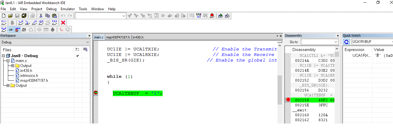
UC1IE |= UCA1TXIE; // Enable the Transmit interrupt
UC1IE |= UCA1RXIE; // Enable the Receive interrupt
_BIS_SR(GIE); // Enable the global interrupt
_BIS_SR(LPM0_bits + GIE); // Going to LPM0
}
//-----------------------------------------------------------------------//
// Transmit and Receive interrupts //
//-----------------------------------------------------------------------//
#pragma vector = USCIAB1TX_VECTOR
__interrupt void TransmitInterrupt(void)
{
UCA1TXBUF = '1';
}
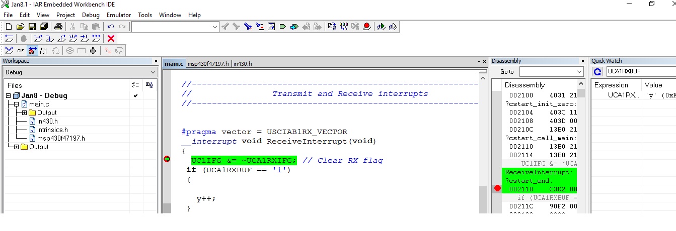
#pragma vector = USCIAB1RX_VECTOR
__interrupt void ReceiveInterrupt(void)
{
UC1IFG &= ~UCA1RXIFG; // Clear RX flag
if (UCA1RXBUF == '1')
{
y++;
}
}
When I have loop back ON the code does not go to the
"
#pragma vector = USCIAB1RX_VECTOR
"
But when it is connected to the Hyper Terminal and sees '1', it goes to the interrupt!