This thread has been locked.

If you have a related question, please click the "Ask a related question" button in the top right corner. The newly created question will be automatically linked to this question.

CCS6 install no longer allows debugging of MSP430G2553 over MSP-FET430UIF

Other Parts Discussed in Thread: MSP430G2553, MSP430F5529, MSP430G2231, MSP430F2618, MSP-GANG

I have been using CCSv5 for a while to develop and debug code to a MSP430G2553.  I am not using a USB link to a Launchpad board.  Instead, I have put a J-Tag terminal on my target PCB board which allows me to use the MSP-FET430UIF.

This has worked very well for a long time.

Unfortunately, I can't seem to debug with CCSv6.  Errors are various, but they all occur when CSS talks to the MSP-FET430UIF.  Most notably, I often get the following:

Error connecting to the target:
The target setup (MSP430F5529) does not match the actual target type (MSP430G2xx3)

As I have not changed any code, I figure this is either (a) a driver issue, or (b) a CCSv6 setting issue.

Just a few obvious things which have been done so far:

1) Clean install of CCSv6.

2) Verified that project settings were imported correctly and that the chip target is indeed the MSP430G2553.

3) Rebooted computer and CSS multiple times to make sure there was not a driver initialization issue.

4) Always hit "Update" to requests by CSS to update the firmware on the MSP-FET430UIF.

5) Checked code and other things that might have indicated that I am using a MSP430F5529.  Found nothing.

My guess is this has something to do with a driver, but I'm not competent to say much about that.  Any light someone can shed on this is appreciated.  Will provide details about my software configuration if you need that.  I'm guessing however that someone must have had the problem before.  (I found other postings which reported the same error message, but they seemed to be caused by issues that do not apply in my case).

Thanks.

  • Additional Data:

    A virgin CSS project with the following main.c was tested:

    int main(void) {
    WDTCTL = WDTPW | WDTHOLD; // Stop watchdog timer
    return 0;
    }
    

    I could get this simple code to debug in CSS a few times, but never twice in a row:  I always had to unplug the USB and re-plug it in, and even that was no guarantee.  The most common error messages were:

    Load Program Error

    File ..... .out: Load failed"

    AND ...

    Error connecting to the target:

    Unknown device

    As mentioned, all of this worked fairly well under my prior CCSv5 install.  

  • Hi Thaddeus,

    Thanks for the post and sorry to hear of your present troubles. I will suspect there is an interaction between your custom hardware and the CCSv6 emulation version, perhaps something timing related. For example, if the connections were working but marginal before, if there is a change in the MSP-FET430UIF emulation version like there would be for the different versions of CCS, I could see there suddenly being an issue like this because the timings may work out differently.

    Here are some questions to try to help narrow down the issue:
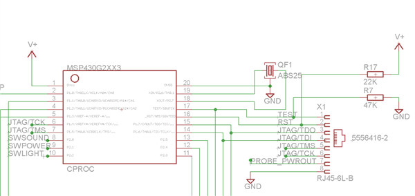
    1. Can you please provide information on the JTAG connections between your MSP-FET430UIF and your custom board? A schematic snippet showing this would be best if possible, including any passives on the lines - pullups, pulldowns, resistors, caps, any other connections on the same pins. JTAG or SBW programming is used? We will be checking these against the diagrams in the hardware tools user's guide SLAU278 www.ti.com/.../slau278
    2. Can you provide information on whether your board is powered from the FET tool (no other power sources) or if it is being powered externally? Is pin 2 or pin 4 of the MSP-FET430UIF connected to Vcc?
    3. Is there only 1 MSP on the target board?
    4. If you use wires to connect the MSP-FET430UIF to a Launchpad board instead of to your custom target board, do you see any issues? Connections would be as follows: FET pin 1 = Launchpad RST/SBWTDIO pin, FET pin 2 = Launchpad Vcc pin, FET pin 7 = Launchpad TEST/SBWTCK pin, FET pin 9 = Launchpad GND pin.
    5. Is there a long signal path between the MSP-FET430UIF and the MSP430 device on your board? The reason I ask is that long wires (e.g. we list no more than 8 inches in the SLAU278 hardware guide I linked above) can mean more capacitance on the lines, which can interfere with device communication.
    6. In CCSv6, please go to Help > About Code Composer Studio. List the Version listed there. In addition, select "Installation Details" and on the "Installed Software" tab, scroll down to "MSP430 Emulators". Report the Version number listed there, and if possible, the first line of text displayed in the box at the bottom. For example, in my CCSv6.1.1 install this says "CI 6.2.1.0 including MSPDebugStack 3.5.1.001". You could repeat this for your working CCSv5 - this will help us know all version information.

    With CCS version 6.1.1.00022 with MSP430 Emulators 6.2.1.0 MSPDebugStack 3.5.2.002, and the MSP-FET430UIF, I used wires to connect to a G2553 device on a Launchpad (instead of using the on-board Launchpad emulation). However, I was unable to reproduce your issue - all worked fine, through multiple programming cycles. Therefore, I am concerned there may be a hardware related component to your problem, hence all of the questions regarding your custom board above.

    Regards,
    Katie
  • Hello Katie,

    Yes, I fear your guess:  Maybe my PCB configuration was only marginally working with CCSv5 and some innocuous change has now tipped it over the edge.  That said, I will answer your questions as best I can below, and then will provide some more data

    1) See attached diagram.  You might wonder about the extra wires going off screen attached to TDO and TDI:  These are connected to high-impedance transistors that are used in another portion of the circuit.  That might be the problem, but it has never given a problem before.  

    2) I can configure the board to be powered by the FET or by its own power supply.  Both modes have always worked with the debugger.  By changing the connector cable between my circuit and the FET, I can direct the PROBE_PWROUT line to either the JTAG Vcc(Tool) pin (for powering by FET) or JTAG Vcc(sense) pin (for powering by my circuit).  Both modes have always worked.  For example, for my MSP430GANG programmer, I let the gang programmer power everything.  Works without fail.

    3) Yes, only one MSP processor on this particular target.

    4) Tested that today with a MSP430G2231.  No problems.  Also tested my MSP-FET430UIF on an old MSP430F2618 Dev board, and then on an MSP430F5529.  All of them debug, so the MSP-FET430UIF is (thankfully) not the problem.

    5) Excellent idea, and I was worried about it.  My custom cord was indeed over 8 inches, so I gave it a trim, and re-wired.  Sad to say, this did not fix the problem.

    6) Version: 6.1.2.00015 for CCS.  The text for "MSP430 Emulators" is "CI 6.2.1.0 including MSPDebugStack 3.5.1.001".  The "MSP430 Compiler Tools" has version 4.4.6.  Unfortunately, in order to avoid driver incompatibilities, I removed CCSv5 from my computer.  (Also had something to do with running out of disk space on my C: drive).

    * * *

    Now, here's another possible idea:  Could there be something with the new CCSv6 install that is now mistaking JTAG 4 wire with SBW ?  Apparently, there is some auto-magical way in which CCS figures out which protocol to use.  Perhaps it is getting confused in my case?  

    One other piece of data:  Elprotronic software seems to be able to communicate with my PCB and I can burn hex images with it ... albeit with an occasional burp.

    Thank you for helping me look into this.  Again, I suspect my PCB board might be the culprit, but I still want to figure out why everything went south with CCSv6. Perhaps some driver changed, or maybe the MSP430UIF firmware is different.  Or maybe the baud rate used has been boosted so that marginally cheesy links will get broken?  Couldn't say.

    Thad.

  • Hi Thad,

    Thanks for the detailed info - it is really helpful.

    Your schematic for your JTAG connections looks pretty good, but I did see that you used a different value pullup on RST than the recommended value. Looks like you have 22k pullup on RST when we recommend 47k - could be a good test to change this to match our recommended value (the RST line is usually the most timing sensitive one, and the tool has to be able to pull down on it in the right timing). You may also want to try to get a reading on how much capacitance is on the RST line - I know you already started shortening your cable, but the RST signal in particular is the one that can be vulnerable to too much capacitance in the system. You also might want to try for testing removing the additional connections on TDO and TDI, again as a test to see if this could be your culprit. If that does prove to be the issue, then you could always change to using SBW programming instead, by using wires to connect up to RST and TEST on your G2xx device, and connecting them in the SBW configuration (RST to fet tool pin 1, TEST to fet tool pin 7) so that the TDO and TDI lines on your G2xx are not being used for programming and could have your other connections.

    The fact that things are working ok with the Elprotronic software strongly makes me suspect a timing issue - the different tools all have slightly different timing. Therefore it would fit with our marginal programming connections theory - I've seen this happen before (where it may work on one tool but not another, because something about the JTAG/SBW connections was on the edge).

    Regards,
    Katie
  • Yes, I did some testing this morning:  Broke connections of TDO and TDI  to other parts of circuit in order to isolate connects with the JTAG.  I also replaced that 22K with a 47K.  No dice.  Still does not work.   As nice as it would be to start using SBW instead of JTAG, I really want to try and figure out why this won't work.

    My theory originally was that it had something to do with changes in the FET firmware.  To test that theory , I downgraded the firmware on the FET from V3 to V2. ( There is a batch script in the ccs_base\DebugServer\drivers directory that does this).

    After doing that I was able to use the Elprotronic debugger without burps.  This then isolates the problem to an incompatibility between my PCB board and the new FET firmware.  As you say, probably timing.

    So short of doing a complete re-design of my PCB boards, I'm now looking for a work around for this legacy project. What I would like to get CCSv6 to let me use this older firmware on the FET.  To do this, I replaced msp430_emu.drv and msp430.DLL with the files from the old CCSv5 directory.

    Problem is, CSS still wants to upgrade the firmware on the FET before allowing me to debug.  I thought reverting the driver would solve this, but it did not.  Is there any way that CSS will allow me to use my old driver/DLL/firmware combo that works? 

    Summary Details:

    1) Trying to use firmware version 2.04.09.001

    2) Trying to use MSP430.dll dated 9/20/2012

    3) Trying to use msp430_emu.drv dated 11/20/2012

    Thad.

  • More Data: Just tried to do run a generic LaunchPad board via the USB connection ... not via JTAG 14 pin connection (which is what I have been doing so far in all cases)

    For my 4 Launchpad MSP-EXP430G2 boards, CCSv6 does not communicate with any of them. I get messages

    Error initializing emulator:
    No USB FET was found

    AND

    Error initializing emulator:
    Not supported by selected Interface or Interface is not initialized

    In all cases, I can still get Elprotronic software to communicate. So between my tests today on my own electricals and this new result, I think the problem is on the PC side. I think we can say that CCS should be able to communicate with the MSP-EXP430G2 boards right?
  • Hi Thad,

    Using an older DLL with newer CCS is not supported or tested, so I would not recommend this as a way forward - it usually causes problems. Also the older DLL may have bugs that were fixed since then. I'm guessing that your MSP-EXP430G2 boards are not working when you are using this older DLL - but if you go back to the original CCS setup were they working ok (hopefully you haven't deleted anything? )

    Regards,
    Katie
  • Hey Katie,

    Honestly, I probably should not have brought up this new result since my primary concern is still with the MSP-FET430UIF.  I will make a second posting if I continue to have problems with the MSP-EXP430G2 and CCSv6.

    But to answer your questions:  Yes, I'm using my original (unmodified) CCSv6 installation for this result.  I can undo any of the changes mentioned above with the DLLs and drivers.

  • Hi Thad,

    I ran your issues by some of our tools team here, and we know you shortened your wires, but could you tell us how long the signal path still is? They are thinking that you are probably still having issues with long wires/capacitance on the lines, and may need to try shortening them even further...

    -Katie
  • Sure: Measuring the "pigtail" it's exactly 8 inches. I could always shorten it some more or change cables entirely. I'm not using a ribbon cable like the one that comes with the FET. Maybe that is part of the problem?

    If indeed this is the culprit, it still leaves the following questions unanswered:
    1) Why does gang programmer always work with my existing cord?
    2) Why does Elprotronic FET-Pro430 work (mostly) using v3 firmware with my existing cord?
    3) Why does Elprotronic FET-Pro430 work (always) using v2 firmware with my existing cord?
  • I would try shortening it to much less than 8 inches - try to keep it as short as you can for your test.

    For your other questions:
    The MSP-GANG is a totally different hardware and software and has different requirements. For the Fet-Pro430 software - all of these software use different timings and sequences even though it is using the same MSP-FET430UIF hardware. If you have marginal connections you may succeed or fail depending on firmware version due to different timing requirements. There are so many variables when someone makes their own board, but we can only test with the TI target boards when we do the firmware releases and updates. Hence why all the connections in the hardware tools user's guide have to be followed very precisely because this really specifies the set of conditions for which we've tested everything. Additional connectors/adaptors, different kinds of wire, etc can all contribute to capacitance on the line - all we can really say is that you need to make sure your capacitance is below 2.2nF for reliable programming (see footnote E on figure 2-1 of the hardware tools user guide www.ti.com/.../slau278 ).

    Regards,
    Katie
  • Update:  I want to follow up on this so the thread is complete.  Most of the problems here were in fact due to the CCSv6 installation.  Since I followed the steps for installation, I'm a bit worried about how things got messed up.  Please see this post for details about installation issues.

    That said, it turns out that the cord length did have something to do with things. I have since made a very short connector (2") to my board, and that appears to be working.  Unanswered is exactly what changed between versions 3 and versions 2 of the FET firmware to make this an issue.  I am noting that right now for the sake of anyone else that might encounter problems on their own PCB design.

**Attention** This is a public forum