This thread has been locked.

If you have a related question, please click the "Ask a related question" button in the top right corner. The newly created question will be automatically linked to this question.

Reading 32-bit SPI with MSP430G2553

Hello! 

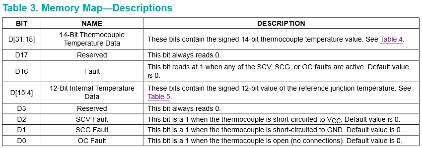
I'm working with thermocouples--and I'm new to the game. I have found a device(MAX31855) from that will read the thermocouple and then communicate the information to the MSP430 via SPI. The problem is as I come up with the logic, I am under the impression that the receive buffer is 8 bits, where the MAX31855 chip has 32 bits of information to give. Is it possible to just read the receive buffer 4 times (after waiting for each receive)?

Any help would be appreciated!

  • Hi Mark!

    Yes, sure! At least in theory you can read as many bytes as you want. For receiving a 32 bit result, you simply receive 4 bytes in a row. This is common practice and no problem at all. It is no coincidence that transmissions of ADC results or whatever are a multiple of 8 bits in most cases.

    Dennis
  • I would read the 4 bytes in to a buffer[4] array.
    i=0;while (i<4) buffer[i++] = UCA0RXBUF;

    Could use a union

    union {
    char buffer[4];
    struct{
     int thermocouple;
     int internal;
     };
    };

    I would first do the bit testing of the fault flags
    if (thermocouple & BIT0)

    And then right shift, it will do sign-extend as the compiler knows it's a signed int.
    thermocouple >>= 2; 
    internal >>= 4;

  • Sorry it took so long to reply--lots of family stuff going on. Thank you all for the answers.

    I thought I had the SPI code ready to go, but I'm running into more trouble. Here is the code:
    int received_ch;

    P1OUT |= BIT5;
    P1DIR |= BIT5;
    P1SEL = BIT1 | BIT2 | BIT4;
    P1SEL2 = BIT1 | BIT2 | BIT4;

    UCA0CTL1 = UCSWRST;
    UCA0CTL0 |= UCCKPH + UCMSB + UCMST + UCSYNC; // 3-pin, 8-bit SPI master
    UCA0CTL1 |= UCSSEL_2; // SMCLK
    UCA0BR0 |= 0x02;
    UCA0BR1 = 0;
    UCA0MCTL = 0; // No modulation
    UCA0CTL1 &= ~UCSWRST;

    P1OUT &= (~BIT5); // Select Device

    while (!(IFG2 & UCA0RXIFG)); // Ready to read
    received_ch = UCA0RXBUF; // Store received data */

    P1OUT |= (BIT5); // Unselect Device

    My trouble is that I'm getting stuck in the while loop with what I have, and I note that there is no interesting data in UCA0RXBUF. Have I set up at least the SPI mode correctly?

  • You have to send a byre to receive one. You only wait for a byte coming in, but this will not happen.

  • I am using a 3 wire SPI, in which the MSP430 only receives data. There is a chip select that must be low-asserted, and a clock per the normal.
  • If your microcontroller is the master, then it generates the clock for the slave for sending it's data. And the clock only starts when initiating a transfer by "sending" a byte, regardless if you really send data to the slave. So even if the SIMO line is not used and therefore not connected, you have to place a byte in the TX buffer to start the transmission. This can be anything from 0 to 255.

    Dennis

  • If you do not use the SIMO line (BIT2), you of course do not have to set the pin to it's special function and can use it for other things.

    For your 32 bit transmission it is something like this:

    uint32_t result;                           // 32 bit result
    uint8_t  counter;                          // Counter for loop
    
    ...                                        // Other stuff
    
    result = 0;                                // Clear result
    P1OUT &= ~BIT5;                            // Select device
    
    for( counter = 0; counter < 4; counter++ ) // Read four bytes
    {
      IFG2 &= ~UCA0RXIFG;                      // Clear pending RX flag
      UCA0TXBUF = 0x00;                        // Send dummy byte
      while( !(IFG2 & UCA0RXIFG) );            // Wait for RX flag to be set
      result |= UCA0RXBUF;                     // Store received byte
    
      if( counter <= 2 )                       // For byte 0, 1 and 2
      {
        result <<= 8;                          // Shift result left by eight
      }
    }
    
    P1OUT |= BIT5;                             // Unselect device

    Or use Tony's approach. This is just one way for doing it without using interrupts.

    Dennis

  • Absolutely. API is simpler to use in cases like this.
    The Master may need to match the Clock-Phase and the Clock-Polarity required by the Slave.
  • Beautiful coding there--brilliant. I'm understanding slowly--but I think I'm getting there. I removed my code and inserted your code and found that it works great (and makes more sense)--but now the same old problems are haunting me. I see values coming into the UCA0RXBUF that make sense--the values just don't seem to make it into the result variable. I'm having this same (novice) problem when I'm working with analog inputs. Any ideas?

    Thanks for all of your contributions!

  • You loop through line #14 four times, the resulting "result" is the bit-wise OR of the four incoming bytes.
    A luge is to change line #1 to read: "uint8_t result[4];"
    And change line #14 to read: "result[counter] = UCA0RXBUF;"
  • I mean a "cluge" or "kludge", not a "luge" ;)
  • OCY's words in code form:

    uint8_t result[4];                         // 32 bit result in 4 single bytes
    uint8_t counter;                           // Counter for loop
    
    ...                                        // Other stuff
    
    P1OUT &= ~BIT5;                            // Select device
    
    for( counter = 0; counter < 4; counter++ ) // Read four bytes
    {
      IFG2 &= ~UCA0RXIFG;                      // Clear pending RX flag
      UCA0TXBUF = 0x00;                        // Send dummy byte
      while( !(IFG2 & UCA0RXIFG) );            // Wait for RX flag to be set
      result[counter] = UCA0RXBUF;             // Store received byte
    }
    
    P1OUT |= BIT5;                             // Unselect device

    Dennis

  • Once you have your 32 bits of received data, you simply have to mask the different information in it - here is the table from the datasheet:

    The 32 bits contain 14 bits of thermocouple temperature data, 12 bits of reference junction temperature data, 4 status bits and 2 bits that are always zero.

    Dennis

  • Gentlemen! 

    I just thought I'd let you know your code really helped me along. I've got the temperature reading coming out like it should. Thanks for all your help guys! For those who look at this thread in the future, this thread is an excellent help on SPI protocol for the MSP430 working with the MAX31855.

  • Great to hear you were successful!

**Attention** This is a public forum