This thread has been locked.

If you have a related question, please click the "Ask a related question" button in the top right corner. The newly created question will be automatically linked to this question.

Need Suggestion for MCU selection for single phase AC power consumption

Other Parts Discussed in Thread: MSP430F67641, MSP430AFE253, MSP430I2040

Hello sir

We are working on measurement AC current and AC voltage meter.

We are use MSP430F6764 1. Which is sense current using shunt resistor.

Below we attached our current sense circuit. We are current measure two different 15A plug using this circuit.

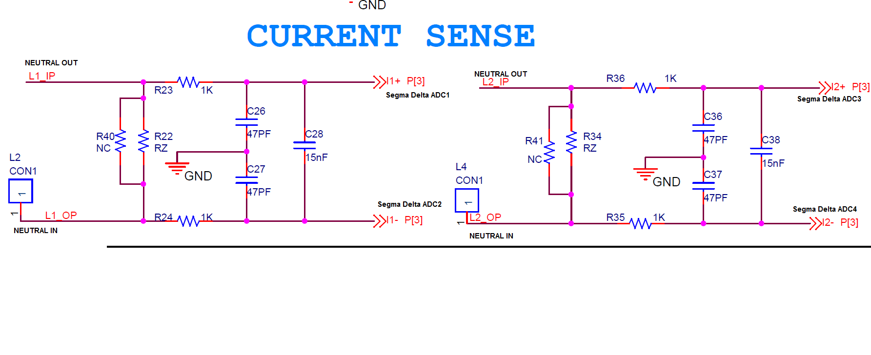
  Please give me suggestion when we use one by one plug the current sense function working proper. But whenever we use both plug simultaneous that time current fluctuation accrue.

Thank you

Regard

Hiren Thumar


  • Your schematic looks OK. The error probably relates to your layout. You didn't give the value of the shunt resistors you are using, but I assume it is something like one milliohm. It doesn't take much wiring in common between the two circuits to drop enough voltage to spoil the readings. It is important to connect the one kiloohm resistors directly to the shunt resistors, and not introduce any further resistance. The terrible temperature coefficient of copper (0.4% per degree Celsius) is another good reason to avoid any copper in the sensed path.

  • Hello Steve,

    Thanks for reply.

    we are use 0.5 milliohm/2W scene resistor in our circuit. we are make this current sense circuit on different general purpose board.after I1+,I1-,I2+,I2- connect our MCU MSP430F67641 sigma delta ADC pin.We are current measure two different 10 A plug using this circuit. we use one by one plug the current sense function working proper. But whenever we use both plug simultaneous that time current fluctuation accrue.

     Do we need any kind of changes in current sense circuit for remove the fluctuation in this circuit??

  • With a 500 micro-ohm shunt you really need to take care about tapping the signal from the very ends of the shunt, because its easy to add significant extra resistance which either has a horrible temperature coefficient, or carries some of the current for multiple load channels. Any resistance in the measured path which is common to multiple load channels will result in crosstalk in the measurements Look at the TI designs using the MSP430AFE253 and MSP430i2040 devices, for embedded metering. These address ways to lay out your circuitry to get good accuracy from a small embedded shunt. Note how the tap off points for the differential signals to the ADC inputs are laid out to get right on to the shunt resistor pads. Poorly laid out versions of those circuits have resulted in more than 10% error over the temperature range, by including some copper in the measured path, and several percent error due to crosstalk between channels.

**Attention** This is a public forum