Dear All,
I am sorry if this question has already been posted. I have found two threads with a similar question, such as this and this. They were useful at the beginning, but I am still concerned about what I am going to explain.
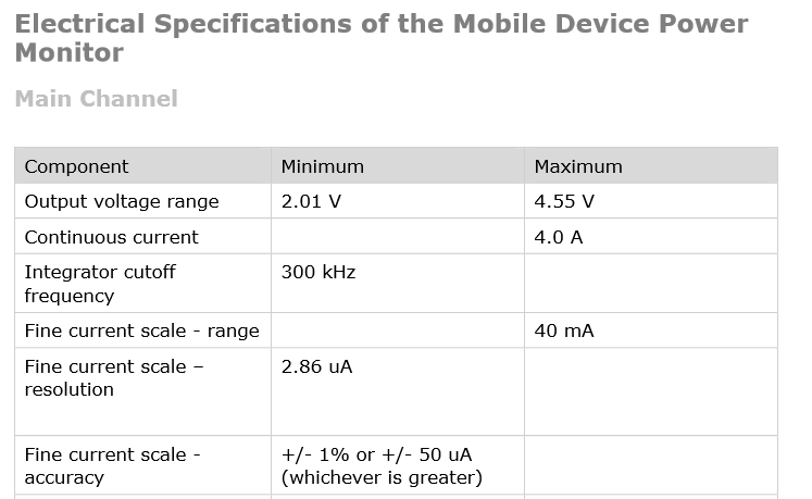
I have been trying to induce the MSP-EXP430FR5739 to enter in LPM4.5 mode. After measuring current consumption with a power monitor (from Monsoon Solutions Inc.) (see Figure 1), I cannot obtain the same current consumption values that are indicated in the device datasheet. On average, these are of the order of 8-14 uA (as seen in the Figure 2).
Figure 1:

Figure 2:

I have followed the user's guide (e.g., section 8.8.3 to enter LPMx.5 modes), but I am not sure of what I am doing wrong any more. At the beginning I though it was a problem of the power monitor and its resolution, but I've seen it can measure values of the order of 0.35 uA (current consumption value for LMP4.5 according to the device datasheet.
My code below:
/*---------------------------------------------------------------------------*/
void
msp430_init_dco(void)
{
  // Startup clock system in max. DCO setting ~8MHz
  // This value is closer to 10MHz on untrimmed parts

  // XT1 Setup
  PJSEL0 |= BIT4 + BIT5;
  PJSEL1 &= ~(BIT4 + BIT5);

  // Set DCO to ~8MHz
  CSCTL0_H = 0xA5;                          /* Enable write access to the CS module */
  CSCTL1 |= DCOFSEL0 + DCOFSEL1;            /* Set max. DCO setting */
  CSCTL2 = SELA_0 + SELS_3 + SELM_3;        /* Set ACLK = XT1; MCLK = DCO */
  CSCTL3 = DIVA_0 + DIVS_0 + DIVM_0;        /* Set all dividers */
  CSCTL4 |= XT1DRIVE_0;                     /* Lowest current consumption for XT1 LF mode */
  CSCTL4 &= ~XT1OFF;                        /* XT1 turns on */

  do
  {
    CSCTL5 &= ~XT1OFFG;
	                                            /* Clear XT1 fault flag */
    SFRIFG1 &= ~OFIFG;
  }while (SFRIFG1&OFIFG);                   /* Test oscillator fault flag */

  CSCTL0_H = 0x01;                          /* Disable access to the CS module */
}
/*---------------------------------------------------------------------------*/
void
watchdog_init(void)
{
  /* The MSP430 watchdog is enabled at boot-up, so we stop it during
     initialization. */
  watchdog_stop();   // This is: WDTCTL = WDTPW | WDTHOLD;

  SFRIFG1 &= ~WDTIFG;	// WDT interrupt flag cleared
  SFRIE1 |= WDTIE; 		// WDT interrupt enabled
}
/*---------------------------------------------------------------------------*/
void
unlock_PMM_module(void)
{
  /* Unlock system by clearing LOCKLPM5 in PM5CTL0 */
  if(SYSRSTIV == SYSRSTIV_LPM5WU) {
    /* Unlock system by clearing LOCKLPM5 in PM5CTL0 */
    PM5CTL0 &= ~LOCKLPM5;
  }
}
/*---------------------------------------------------------------------------*/
void
init_ports(void)
{
  REFCTL0 |= REFTCOFF;
  REFCTL0 &= ~REFON;

  P1SEL0 = 0;
  P1SEL1 = 0;

  P2SEL0 = 0;
  P2SEL1 = 0;

  P3SEL0 = 0;
  P3SEL1 = 0;

  P4SEL0 = 0;
  P5SEL1 = 0;

  PJSEL0 = 0;
  PJSEL1 = 0;

  P1DIR = 0;
  P1OUT = 0;
  P1REN = 0xFF;

  P2DIR = 0;
  P2OUT = 0;
  P2REN = 0xFF;

  P3DIR = 0;
  P3OUT = 0;
  P3REN = 0xFF;

  P4DIR = 0;
  P4OUT = 0;
  P4REN = 0xFF;

  PJDIR = 0;
  PJOUT = 0;
  PJREN = 0xFF;


  P1IE = 0;
  P2IE = 0;
  P3IE = 0;
  P4IE = 0;
}
/*---------------------------------------------------------------------------*/
void
enable_interrupt_LPMx_5(void)
{
  /* Important: P4.0 is connected to button S1
   * P4.1 is connected to both button S2 and VREG_EN pin of
   * CC2520EM radio.
   */
  P4OUT |= BIT0;                     // Configure pullup resistor
  P4DIR &= ~(BIT0);                  // Direction = input
  P4REN |= BIT0;                     // Enable pullup resistor
  P4IES &= ~(BIT0);                  // P4.1 Lo/Hi edge interrupt
  P4IE = BIT0;                       // P4.1 interrupt enabled
  P4IFG = 0;                         // P4 IFG cleared
}
/*---------------------------------------------------------------------------*/
void
msp430_enter_LPMx_5(unsigned char LPM_bits)
{
  init_ports();
  enable_interrupt_LPMx_5();             /* Enable interrupt to wake up from LPMx.5 */

  PMMCTL0_H = PMMPW_H;                   /* Unlock PMMPW register */
  PMMCTL0_L |= PMMREGOFF;                /* Set PMMREGOFF -> LDO turned off on LPMx.5 entry */
  PMMCTL0_L &= ~(SVSHE + SVSLE);         /* Disable SVS */
  _BIS_SR(LPM_bits);                     /* Enter LPMx.5 */
}
/*---------------------------------------------------------------------------*/
void
msp430_cpu_init(void)
{
  _DINT();   // Disable interrupts
  unlock_PMM_module();  // Clear LOCKLPM5
  watchdog_init(); // Initiate watchdog
  init_ports();  // Initiate ports
  msp430_init_dco(); // Initiate DCO and crystal oscillator
  _EINT();   // Enable interrupts
}
/*---------------------------------------------------------------------------*/

/*
 * main.c
 */
int
main(void)
{
  msp430_cpu_init();
  msp430_enter_LPMx_5(LPM4_bits + GIE);
  return 0;
}
I'd appreciate suggestions or hints. Many thanks,
Best wishes,
David