This thread has been locked.

If you have a related question, please click the "Ask a related question" button in the top right corner. The newly created question will be automatically linked to this question.

I2C ISR come only once in MSP430F6779A


Dear All,

I am trying to write data into 2 Kbyte EEPROM interface with my MSP430F67779A using I2C.

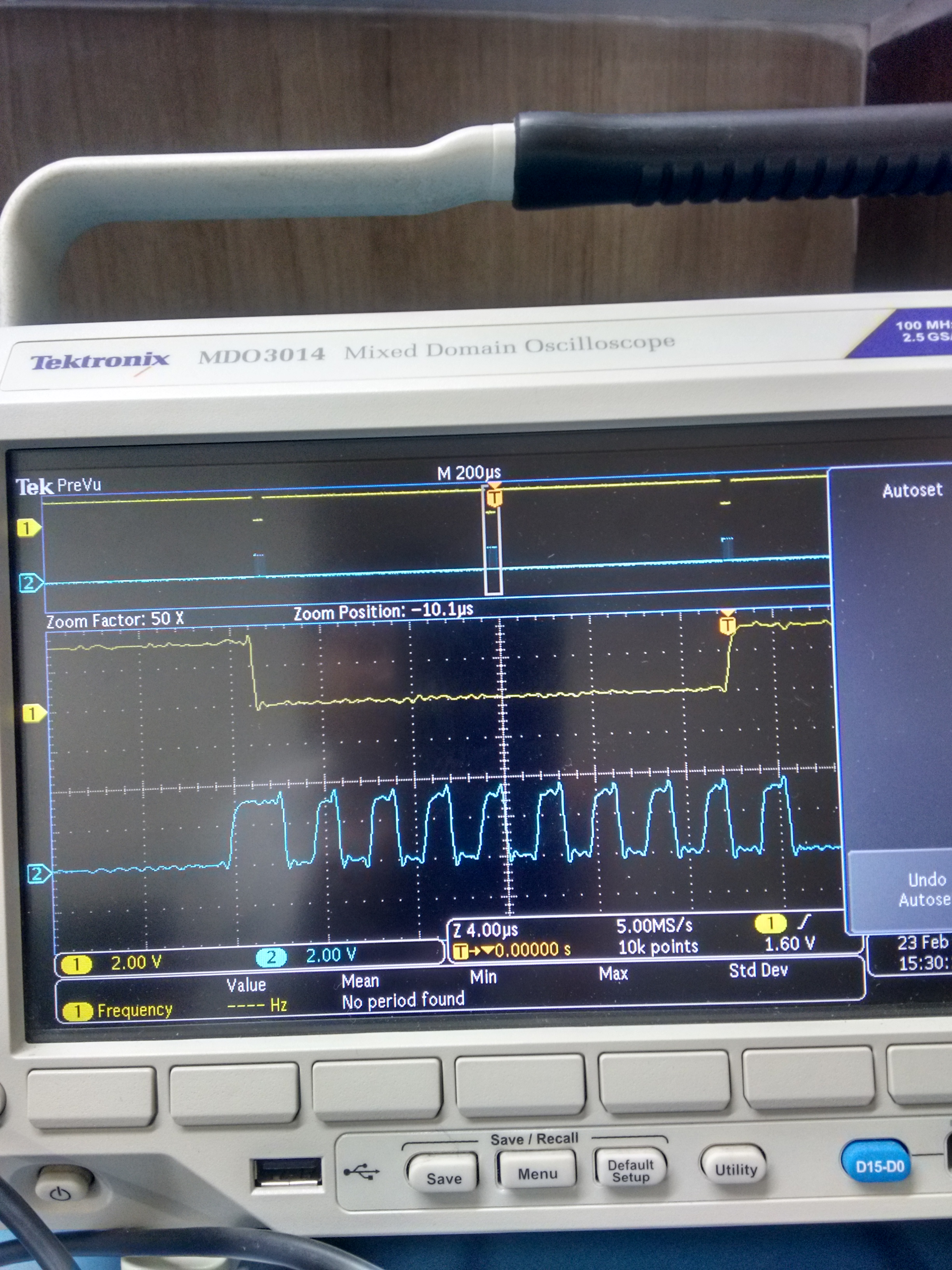
Hardware connection is perfect and generating I2C clock of 400 KHz looking perfect.

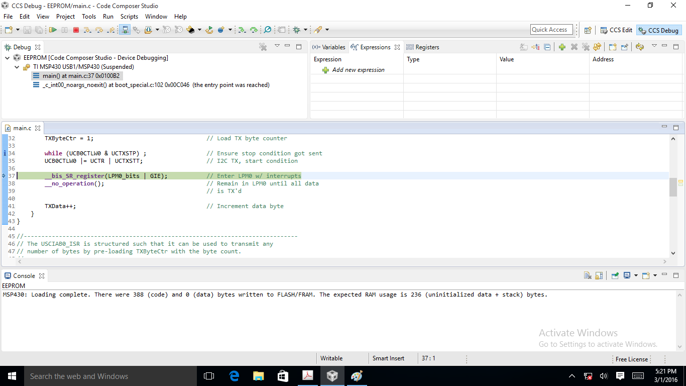
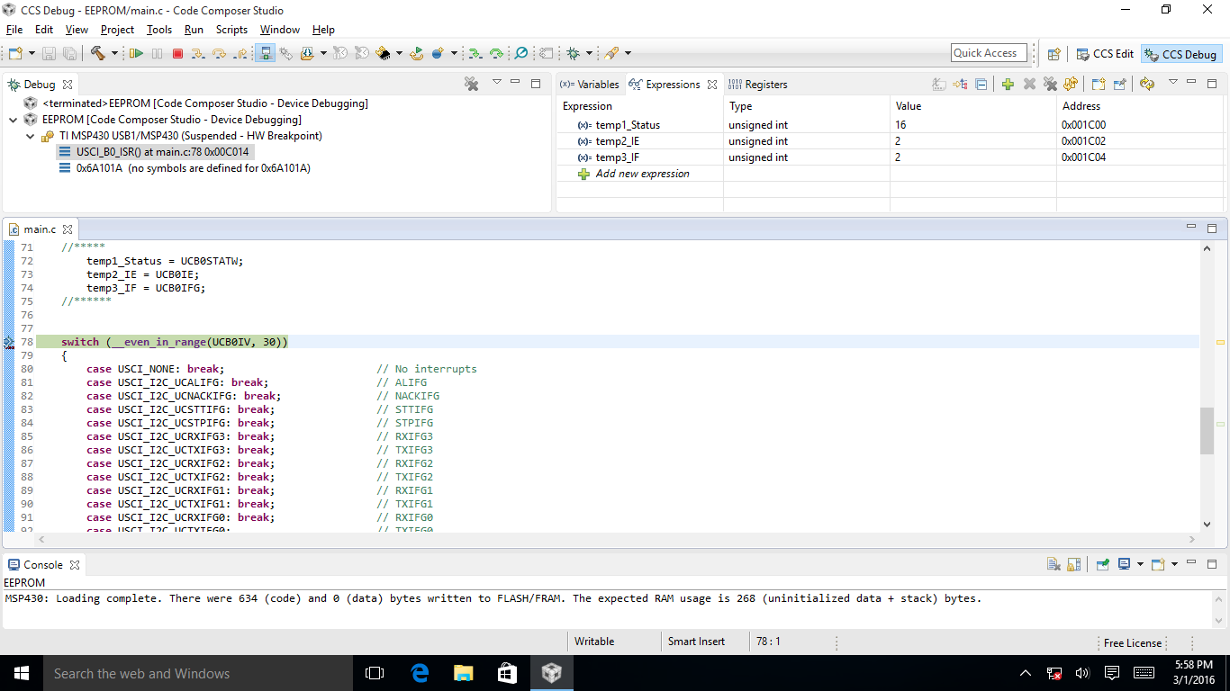
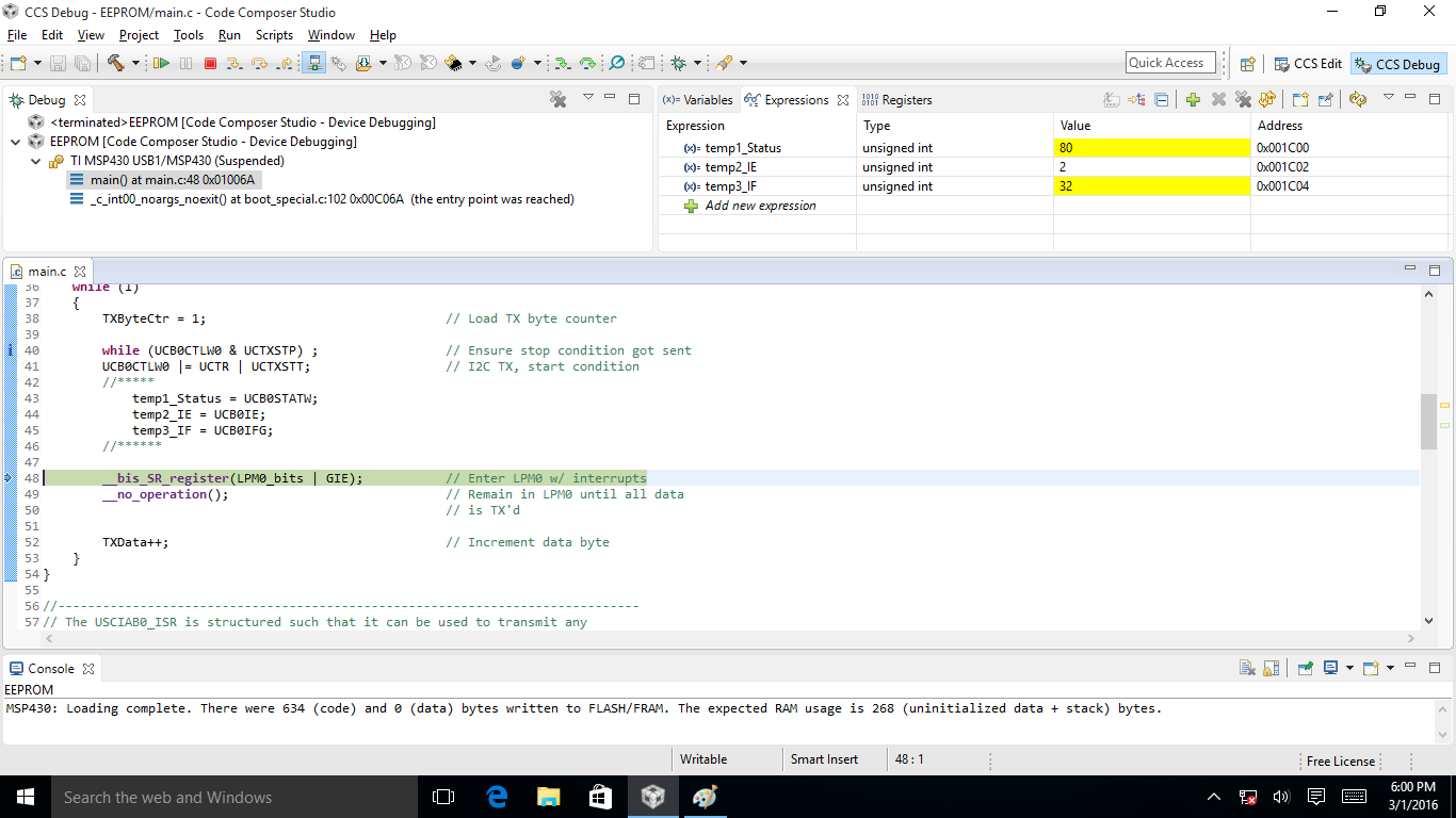
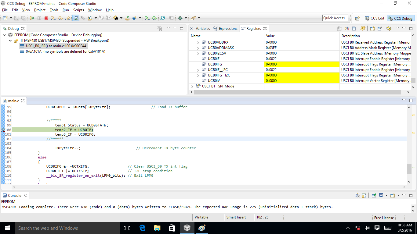
I am trying to write 0x12h data on 0x0000h location of EEPROM. so after I2C initialization and start I2C, in MSP430 It is going once in ISR and send only higher byte of address and then never come ISR.

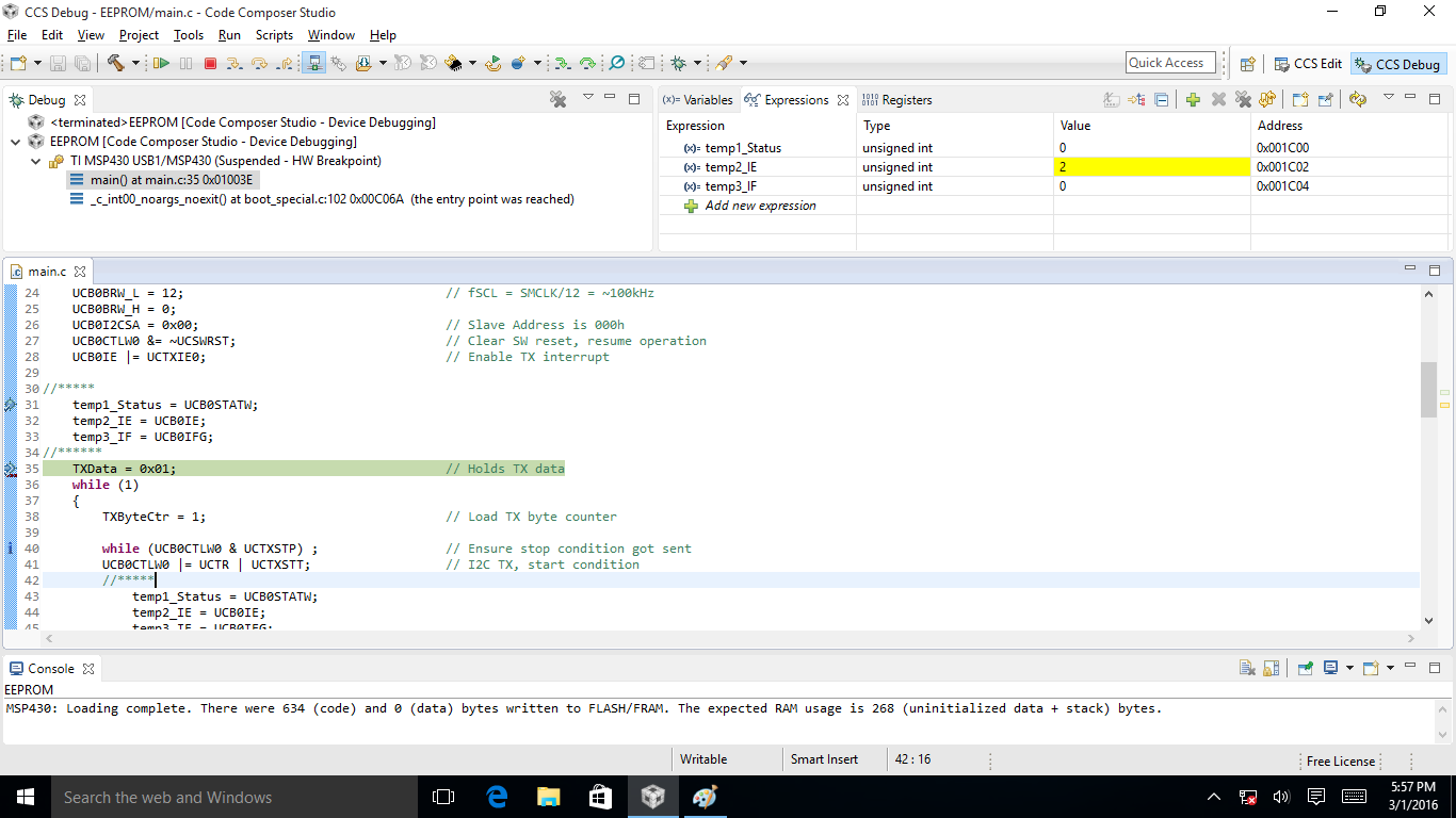
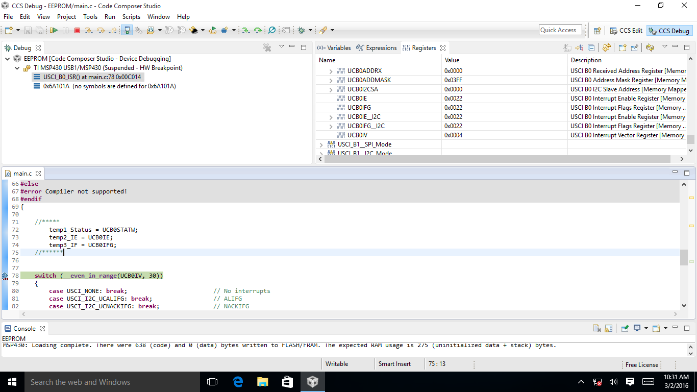
I check interrupt flag register value of I2C which is clear. (00).

Also check Tx buffer value which is clear(00).

and Interrupt enable register (which shows set bit for I2C interrupt.

and If I repeat the I2C start condition generation, then controller going in ISR.

Please guide me.

  • Hi!

    You maybe should post your code so someone can have a look at it.

    Dennis
  • Hi ,

    Please look into the code.

    thanks

    #include <msp430.h>

    int PtrTransmit,again = 1;
    unsigned char I2CBufferArray[66];
    unsigned char I2CBuffer;

    void UCS_config();
    void I2C_config();
    void EEPROM_ByteWrite(unsigned int, unsigned char);

    void main(void)
    {
    WDTCTL = WDTPW | WDTHOLD; // Stop WDT

    UCS_config();
    I2C_config();

    __bis_SR_register(GIE);

    EEPROM_ByteWrite(0x0800, 0x12);

    __delay_cycles(10000);

    for(;;)
    {

    }
    }

    void UCS_config(void)
    {
    PMMCTL0_H = 0xA5;
    PMMCTL0_L = 0x03;
    UCSCTL0 = UCSCTL0 | 0x1F00;
    UCSCTL1 = UCSCTL1 & 0x0000;
    UCSCTL1 = UCSCTL1 | 0x0040;
    UCSCTL2 = UCSCTL2 & 0x0000 ; // FLL Divider
    UCSCTL2 = UCSCTL2 | 0x304F ; // for 20 MHz MCLK and 2.6 MHz SMCLK
    UCSCTL3 = 0x0000;

    UCSCTL4 = UCSCTL4 & 0X0000;
    UCSCTL4 = UCSCTL4 | 0X0043;

    P1SEL0 = P1SEL0 | 0X34;
    // P1SEL1 = P1SEL1 & 0XCB;
    P1DIR = P1DIR | 0X34;
    // CPBD = 0X00;
    }

    void I2C_config(void)
    {
    // Setup P2.5 UCB0SCL, P2.6 UCB0SDA
    P2SEL0 |= BIT5 | BIT6; // Set P2.5,P2.6 to UCB0SCL, UCB0SDA

    // Setup eUSCI_B0

    UCB0CTLW0 |= UCSWRST; // Enable SW reset
    UCB0CTLW0 |= UCMST | UCMODE_3 | UCSSEL_2; // I2C Master, use SMCLK

    UCB0BRW_L = 6; // fSCL = SMCLK/12 = ~100kHz
    UCB0BRW_H = 0;
    UCB0I2CSA = 0x0000; // Slave Address is 00h
    UCB0I2COA0 = 0x0001; // I2C Own address
    UCB0CTLW0 &= ~UCSWRST; // Clear SW reset, resume operation
    // UCB0IE |= UCTXIE0; // Enable TX interrupt
    // TXData = 0xAF; // Holds TX data
    }

    void I2CWriteInit(void)
    {
    UCB0CTL1 |= UCTR; // UCTR=1 => Transmit Mode (R/W bit = 0)
    UCB0IFG &= ~UCTXIFG;
    UCB0IE &= ~UCRXIE0; // disable Receive ready interrupt
    UCB0IE |= UCTXIE0; // enable Transmit ready interrupt
    }

    void EEPROM_ByteWrite(unsigned int Address, unsigned char Data)
    {
    unsigned char adr_hi;
    unsigned char adr_lo;

    while (UCB0STAT & UCBUSY); // wait until I2C module has
    // finished all operations.

    adr_hi = Address >> 8; // calculate high byte
    adr_lo = Address & 0xFF; // and low byte of address

    I2CBufferArray[2] = adr_hi; // Low byte address.
    I2CBufferArray[1] = adr_lo; // High byte address.
    I2CBufferArray[0] = Data;
    PtrTransmit = 2; // set I2CBufferArray Pointer

    I2CWriteInit();
    UCB0CTL1 |= UCTXSTT; // start condition generation
    // => I2C communication is started
    __bis_SR_register(GIE); // Enter LPM0 w/ interrupts LPM0_bits |
    // UCB0CTL1 |= UCTXSTP; // I2C stop condition
    // while(UCB0CTL1 & UCTXSTP); // Ensure stop condition got sent


    }


    //------------------------------------------------------------------------------
    // The USCIAB0_ISR is structured such that it can be used to transmit any
    // number of bytes by pre-loading TXByteCtr with the byte count.
    //------------------------------------------------------------------------------
    // USCI_B0 interrupt service routine
    #if defined(__TI_COMPILER_VERSION__) || defined(__IAR_SYSTEMS_ICC__)
    #pragma vector = USCI_B0_VECTOR
    __interrupt void USCI_B0_ISR(void)
    #elif defined(__GNUC__)
    void __attribute__ ((interrupt(USCI_B0_VECTOR))) USCI_B0_ISR (void)
    #else
    #error Compiler not supported!
    #endif
    {
    if(UCB0IV == USCI_I2C_UCTXIFG0) // TXIFG0
    {
    UCB0TXBUF = I2CBufferArray[PtrTransmit];// Load TX buffer
    PtrTransmit--; // Decrement TX byte counter
    // UCB0IFG &= ~UCTXIFG; // Clear USCI_B0 TX int flag

    temp1 = UCB0IE;
    temp2 = UCB0IFG;

    if(PtrTransmit < 0)
    {
    UCB0IE &=~UCTXIE0; // disable interrupts.
    UCB0CTL1 |= UCTXSTP; // I2C stop condition
    again =1;
    PtrTransmit = 2;

    while(UCB0CTL1 & UCTXSTP); // Ensure stop condition got sent
    }
    }
    }

  • Hi,

    Any one looked into this?

    waiting for someone help.

    Regards

    Bhavdipsinh

  • Hi, ,
    Please look into the code. I have tried example code of MSPware but not getting result.
    Please help me.
    Regards
    Bhavdipsinh
  • Hi,

    Is there not any TI Employee who responsible to guide.

    I need inputs from TI member for it.

    Regards

    Bhavdipsinh

  • Please look into attached waveform where blue line shows clock and yellow line shows data. this is come only once.

    Please guide.

    No one from TI has idea for solution. I have Pull-up data and clock pin of I2C. all other configuration and code is in previous post.

    Regards

    Bhavdipsinh

  • Hi Bhavdipsinh,

    the first issue I see already in the init procedure of the PMM

    PMMCTL0_H = 0xA5;

    PMMCTL0_L = 0x03;

    This is not according the user's guide of setting Vcore up to level 3.

    Doing this like you did it is not ensured that code execution will work as expected! Please use the procedure described in user's guide or even better use the DriverLib which you can download from TI web

    If you have corrected it and the issue still appears please let me know.

    Best regards,

    Dietmar

  • Hi Deitmar,

    Thanks for your reply and suggestion.

    I check below attached code for I2C write (use MSPWare example), change slave address to 0x00h (As per my EEPROM address).

    Still same, ISR comes only once and code doesnot work properly.

    I am using EEPROM of ST M24C16-W.

    waiting for your reply.

    Regards

    Bhavdipsinh

    //
    //   E. Chen
    //   Texas Instruments Inc.
    //   January 2014
    //   Built with CCS Version: 5.5.0 and IAR Embedded Workbench Version: 5.52
    //******************************************************************************
    #include <msp430.h>
    
    unsigned char TXData;
    unsigned char TXByteCtr;
    
    void main(void)
    {
        WDTCTL = WDTPW | WDTHOLD;                         // Stop WDT
    
        // Setup P2.5 UCB0SCL, P2.6 UCB0SDA
        P2SEL0 |= BIT5 | BIT6;                             // Set P2.5,P2.6 to UCB0SCL, UCB0SDA
    
        // Setup eUSCI_B0
        UCB0CTLW0 |= UCSWRST;                             // Enable SW reset
        UCB0CTLW0 |= UCMST | UCMODE_3 | UCSSEL_2;         // I2C Master, use SMCLK
    
        UCB0BRW_L = 12;                                   // fSCL = SMCLK/12 = ~100kHz
        UCB0BRW_H = 0;
        UCB0I2CSA = 0x00;                                 // Slave Address is 000h
        UCB0CTLW0 &= ~UCSWRST;                            // Clear SW reset, resume operation
        UCB0IE |= UCTXIE0;                                // Enable TX interrupt
        TXData = 0x01;                                    // Holds TX data
    
        while (1)
        {
            TXByteCtr = 1;                                // Load TX byte counter
    
            while (UCB0CTLW0 & UCTXSTP) ;                 // Ensure stop condition got sent
            UCB0CTLW0 |= UCTR | UCTXSTT;                  // I2C TX, start condition
    
            __bis_SR_register(LPM0_bits | GIE);           // Enter LPM0 w/ interrupts
            __no_operation();                             // Remain in LPM0 until all data
                                                          // is TX'd
    
            TXData++;                                     // Increment data byte
        }
    }
    
    //------------------------------------------------------------------------------
    // The USCIAB0_ISR is structured such that it can be used to transmit any
    // number of bytes by pre-loading TXByteCtr with the byte count.
    //------------------------------------------------------------------------------
    // USCI_B0 interrupt service routine
    #if defined(__TI_COMPILER_VERSION__) || defined(__IAR_SYSTEMS_ICC__)
    #pragma vector = USCI_B0_VECTOR
    __interrupt void USCI_B0_ISR(void)
    #elif defined(__GNUC__)
    void __attribute__ ((interrupt(USCI_B0_VECTOR))) USCI_B0_ISR (void)
    #else
    #error Compiler not supported!
    #endif
    {
        switch (__even_in_range(UCB0IV, 30))
        {
            case USCI_NONE: break;                        // No interrupts
            case USCI_I2C_UCALIFG: break;                 // ALIFG
            case USCI_I2C_UCNACKIFG: break;               // NACKIFG
            case USCI_I2C_UCSTTIFG: break;                // STTIFG
            case USCI_I2C_UCSTPIFG: break;                // STPIFG
            case USCI_I2C_UCRXIFG3: break;                // RXIFG3
            case USCI_I2C_UCTXIFG3: break;                // TXIFG3
            case USCI_I2C_UCRXIFG2: break;                // RXIFG2
            case USCI_I2C_UCTXIFG2: break;                // TXIFG2
            case USCI_I2C_UCRXIFG1: break;                // RXIFG1
            case USCI_I2C_UCTXIFG1: break;                // TXIFG1
            case USCI_I2C_UCRXIFG0: break;                // RXIFG0
            case USCI_I2C_UCTXIFG0:                       // TXIFG0
                if (TXByteCtr)                            // Check TX byte counter
                {
                    UCB0TXBUF = TXData;                   // Load TX buffer
                    TXByteCtr--;                          // Decrement TX byte counter
                }
                else
                {
                    UCB0IFG &= ~UCTXIFG;                  // Clear USCI_B0 TX int flag
                    UCB0CTL1 |= UCTXSTP;                  // I2C stop condition
                    __bic_SR_register_on_exit(LPM0_bits); // Exit LPM0
                }
                break;
            case USCI_I2C_UCBCNTIFG: break;               // CNTIFG
            case USCI_I2C_UCCLTOIFG: break;               // LTOIFG
            case USCI_I2C_UCBIT9IFG: break;               // BIT9IFG
            default: break;
        }
    }


  • Bhavdipsinh,

    does this behavior appear on all units or only on some?
    The other questions is can you reproduce this behavior also under debug and if yes can you find out where the device hangs?
    Does it stay in LPM?

    Best regards,
    Dietmar
  •   Hi Dietmar,

    Thanks for your prompt reply.

    I checked this code with my 2 different prototype boards and have same behavior.

    Yes, It stay in LPM mode. but It goes once in I2C ISR then stuck at LPM.

    Please find attached screen shot of debug which shows both situations.

    Regards

    Bhavdipsinhd

  • Bhavdipsinhd,

    ok looks like it is systematic issue and thanks for sharing the CCS screenshots.
    Looks like an interrupt is not enabled or a flag gets not cleared correctly.

    So can you please provide screenshots of the Status Register settings and the USCI register values for the first case and for 2nd failing case. It's important for me to check if something is wrong. Sorry for pushing for further information but this is required to find the root cause.

    Thanks,
    Dietmar
  • Thanks Dietmar for your reply and guidance.

    Please find below attached screen shots in which I take status, Interrupt Enable and Interrupt Flag resisters values at different instants sequential.

    I think which help you to give your best solutions.

    Thanks and Regards

    Bhavdipsinh

  • Bhavdipsinh,

    except writing the registers to a variable you also can use the register view to make the values easier to read.
    So in your 1st scenario a TXIFG is set and because this interrupt is enabled it gets executed.
    The 2nd scenario you see 32 in the UCB0IFG register which means the UCNACKIFG is set because this interrupt is not enabled the ISR is not executed. Maybe you should enable this interrupt in the UCB0IE register.

    The point is that you use the MSP430 in master mode right based on user's guide page #1007 an ACK is expected. So is this really send by the EEPROM?

    Best regards,
    Dietmar
  • Hi Dietmar,

    Yes, In EEPROM datasheet, they mentioned that the EEPROM give Ack at each byte on 9th number clock cycle.
    I will enable Ack interrupt and reply you back.

    Thanks for your suggestions.
    Bhavdipsinh
  •       Hi Dietmar,

    I have enable Ack interrupt and debug code but result is same.

    Please find herewith attached sequences screenshots and Waveform of CLK and Data pin output of I2C.

    I understand below points from it. Let me correct or give your inputs.

    1. In first Screen shot, Vector resistor value and Flag value indicate the interrupt for ACK after start I2C.

    2. In second Screen shot, Vector resistor value and Flag value indicate the interrupt for I2C Tx.

    3. In third Screen shot, Flag clears after serving interrupt.

    4. In forth, Again stuck at LPM and at same time you can see the resistors value.

    Please give your inputs.

    Regards

    Bhavdipsinh

  • Bhavdipsinh,

    assume that you mean registers when to talk about resistors right? ;-)

    Yes your understanding is right:

    1. in the first screenshot UCTXIFG0 and UCNACKIFG are set because UCB0IV is 0x04 the Not acknowledgment part of the ISR is executed.
    In your code it does nothing except clearing the IFG automatically.

    2. Then in the 2nd screenshot only the UCTXIFG0 is that and UCB0IV is 0x18 which means that the Transmit buffer empty and the corresponding data were transmitted.

    3.in the 3rd screenshot you can see that you successfully clear the UCTXIFG0

    4. because no additional flags will be set it hangs in LPM

    The question is why sending an additional byte will not work or in other words why I2C will not shift again to empty the TX buffer.
    In the "code i2c.txt" you attached earlier the variable TXByteCtr was set to 1 means you transmit one byte.
    See also the comment above the ISR.

    //------------------------------------------------------------------------------
    // The USCIAB0_ISR is structured such that it can be used to transmit any
    // number of bytes by pre-loading TXByteCtr with the byte count.
    //------------------------------------------------------------------------------

        switch (__even_in_range(UCB0IV, 30))
        {
            case USCI_NONE: break;                        // No interrupts
            case USCI_I2C_UCALIFG: break;                 // ALIFG
            case USCI_I2C_UCNACKIFG: break;               // NACKIFG
            case USCI_I2C_UCSTTIFG: break;                // STTIFG
            case USCI_I2C_UCSTPIFG: break;                // STPIFG
            case USCI_I2C_UCRXIFG3: break;                // RXIFG3
            case USCI_I2C_UCTXIFG3: break;                // TXIFG3
            case USCI_I2C_UCRXIFG2: break;                // RXIFG2
            case USCI_I2C_UCTXIFG2: break;                // TXIFG2
            case USCI_I2C_UCRXIFG1: break;                // RXIFG1
            case USCI_I2C_UCTXIFG1: break;                // TXIFG1
            case USCI_I2C_UCRXIFG0: break;                // RXIFG0
            case USCI_I2C_UCTXIFG0:                       // TXIFG0
                if (TXByteCtr)                            // Check TX byte counter
                {
                    UCB0TXBUF = TXData;                   // Load TX buffer
                    TXByteCtr--;                          // Decrement TX byte counter
                }
                else
                {
                    UCB0IFG &= ~UCTXIFG;                  // Clear USCI_B0 TX int flag
                    UCB0CTL1 |= UCTXSTP;                  // I2C stop condition
                    __bic_SR_register_on_exit(LPM0_bits); // Exit LPM0
                }
                break;
            case USCI_I2C_UCBCNTIFG: break;               // CNTIFG
            case USCI_I2C_UCCLTOIFG: break;               // LTOIFG
            case USCI_I2C_UCBIT9IFG: break;               // BIT9IFG
            default: break;
        }

    So please align the number of bytes and let me know if it works.

    Best regards,

    Dietmar

  • Bhavdipsinh,

    As Dietmar pointed out, are are receiving a NACK interrupt from your slave. the slave is supposed to send an ACK when it receives data correctly, and will send a NACK when it does not. I recommend enabling these interrupt flags and placing a trap in the ISR for them to see exactly where it is getting stuck.

    For example:
    case USCI_I2C_UCNACKIFG:
    while(1);
    break; // NACKIFG

    with the above modification, when you receive a NACK, the code will be stuck in that ISR. this is for debugging only of course. Do you ahve a logic analyzer available for you to use? It will be very informative to see what is being sent on the I2C lines themselves and will make this debug effort easier.

    If your slave device is sending a NACK in response to the MSP430, that means what you have sent is not being recognized by the slave. Please double check your slave devices documentation to ensure you have the correct slave address and are sending the correct intial byte tot he slave.

    Regards,
    JH
  • Hi Dietmar,

    Thanks for your continue support.

    We shortout the problem.

    I found that I need to set 0x50h as slave address instead of 0x00h or 0xA0h because 1 1010 000 0     first bit for start, next four bits 1010 for EEPROM default and next three 000 for A2,A1,A0 and last for read/Write. I need to consider it as 1101 0000    instead of 1   1010  0000  So after setting it in slave address resistor its working perfect.

     Please find find attached result FYR.

    Thanks for your response and guidance.

    Regards

    Bhavdipsinh

  • Bhavdipsinh,

    great to hear that you were able to solve it and also good that it's related to slave address and not the eUSCI or EEPROM itself.

    So hope you increased your I2C experience by this exercise. Good luck for your project.

    Best regards,
    Dietmar

**Attention** This is a public forum