This thread has been locked.

If you have a related question, please click the "Ask a related question" button in the top right corner. The newly created question will be automatically linked to this question.

Reset on EMI / ESD and TEST/SBWTCK pin termination

Other Parts Discussed in Thread: CC430F5137, CC1101, MSP430FR6972, MSP-FET

Hi Everybody,

I had a lot of problem until I found the cause, it take me a long time to trace it down.

It's the floating input TEST pin.

It is recommended to left the TEST pin unconnected. But the TEST pin is need in the factory to program the MSP430 with the Spy-Bi-Wire.

This TEST pin is very sensitive and picks up EMI very easy and the MSP430 behaves erratic, like resetting itself.

I came up with a solution the solves the EMI problem and still be able to run the Spy-Bi-Wire correctly. Infact the Spy-Bi-Wire works as well better with this configuration.

In the end of the trace I have add a 1k resistor to ground and a 1nF capacitor to ground.


Now to my questions:
1. It is recommended to left the TEST pin unconnected. Why?
2. Seems the TEST pin is a input, I can as well short it to ground and that solves the EMI problem too. Is there any problem with that?

I appreciate any comment on my solution and questions?

Regards,

Rene  

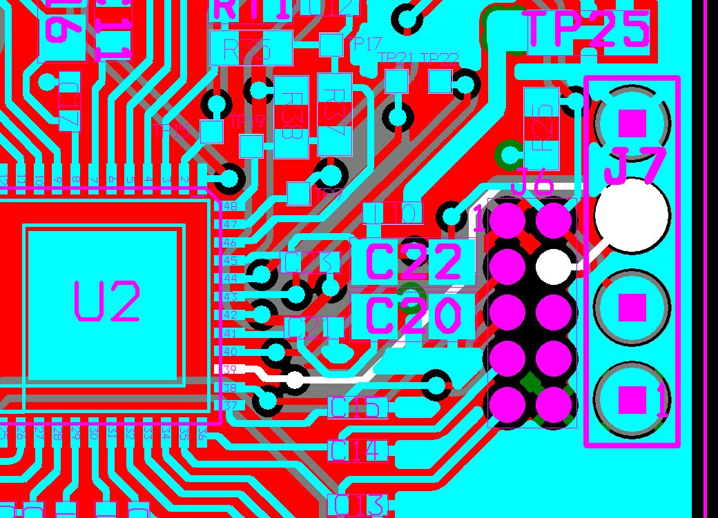
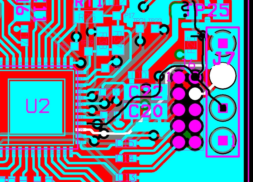
  • It may be helpful if you tell us (a) which MSP chip you are using, (b) the silicon revision, (c) the PCB layout of the area near the signal TEST/SBWTCK, and (d) the EMI environment.

    Rene Baumann said:
    1. It is recommended to left the TEST pin unconnected. Why?

    This pin has an internal pull-down resister, thus normally does not need to have external pull-down.

    Rene Baumann said:
    2. Seems the TEST pin is a input, I can as well short it to ground and that solves the EMI problem too. Is there any problem with that?

    Correct. Except you will need to remove the short to ground when you use SBW, 4-wire JTAG, or BSL.

  • (a)  CC430F5137

    (b)  DIE Revision E

    (c)  4 layer PCB, a homogeneous ground and power plane, top and bottom layer are used for routing.  

    (d)  I use a normal FL lamp and a EDS pistol, both of them can easy disrupt the MSP430. We have a lot of problems at the customer.

    old_cow_yellow

    This pin has an internal pull-down resister, thus normally does not need to have external pull-down.

    I think this pull-down resistor is far too weak.

    old_cow_yellow

    Correct. Except you will need to remove the short to ground when you use SBW, 4-wire JTAG, or BSL.

    Yes I agree. But that is ok, we have many units installed by the customer that we need to have a fix for and this is the most easy one. Just short the TEST/SBWTCK to ground.

    Regards,

    Rene

  • Hi Rene!

    Beside from your TEST pin, what are the connections made to your RST one (pin 40)?

    I can see it leads to R25 which is connected to an inner layer, so will be DVcc. And there is a trace going away upwards. Is there a filter capacitor somewhere far away from the device's pin?

    Dennis

  • Yes, there is a filter capacitor and a reset button. I must say the filter capacitor is not optimal placed. But after a lot of experiment it all come down to the TEST pin. See the reset schematics the schematic below.

    I have 3 other PCB design with the same MCU that have the same problem and they all have a different routings.

    Regards,

    Rene

  • Hi Rene,

    what kind of erratic behaviors did you experienced during ESD testing?

    Did you performed ESD testing according IEC 61000-4-2?

    If "only" unwanted resets appeared did you analyze the SYSRSTIV register to analyze what kind of reset sourced triggered it?

    Did you tried to switch RSTNMI to NMI function and checked again?

    Best regards,
    Dietmar

  • Hi Dietmar,

    what kind of erratic behaviors did you experienced during ESD testing?
    Did you performed ESD testing according IEC 61000-4-2?

    I do not have the proper equipment to test exactly according to IEC 61000-4-2 standard. But I have a setup that I can simulate the problem we have at the customer. I use a standard FL lamp and a ESD pistol up to 8kv.  

    The environment at the customer side is typically a office building and Hotels.

    If "only" unwanted resets appeared did you analyze the SYSRSTIV register to analyze what kind of reset sourced triggered it?

    Did you tried to switch RSTNMI to NMI function and checked again?

    Yes I did read the SYSRSTIV register. On a normal startup I get a 02 "BOR" and on a interference I get a 04 "RST/NMI (BOR)".

    That brings me to the idéa to change RST to NMI. That work somewhat and we still get many units that hang up itself at the customer. So I need to find the cause of the problem. And what I found is to terminate the TEST/SBWTCK pin with a 1nF capacitor and 1k resistor to ground, this works best.


    Best regards,

    Rene


  • Rene,

    thanks for additional information! So you said when you configured RSTNMI to NMI the resets disappeared but then some hang-up behavior appeared right?

    Some more questions:

    1. When you configured RSTNMI pin to NMI function did you handled the NMI event properly in SW?

    2. When you said hang-up, does it mean the CPU stopped execution or does the device hang in any kind SW loop?
    -> please check if it not hangs in the LFO fault flag check loop
    -> when it hangs does the WDT was able to recover the device and bring it back to operation
    -> what was the current consumption in hang-up state

    The TEST pin itself has normally a ~35 kOhm pull down connected internally with and external pull down of 1 kOhm you make this pull down connection even stronger. The RST pin is next to the TEST pin so noise on this line might couple to the RSTNMI pin. Do you have checked the layout for this?

    Best regards,
    Dietmar

  • Hi Dietmar,

    Hm very good questens!

    thanks for additional information! So you said when you configured RSTNMI to NMI the resets disappeared but then some hang-up behavior appeared right?

    The hang-up behavior has always been the problem. The difference is when the RSTNMI is configured to NMI, the resets disappeared but the unit still hang-up but less often. And those not solve the problem.
    When a unit hang-up it is mostly enough to just re-power the unit. But in rare case is a total hang-up, and can only be restored by reloading the FW.

    1. When you configured RSTNMI pin to NMI function did you handled the NMI event properly in SW?

    // Initialize Reset pins for NMI
    // -----------------------------
    //
    // This code is do handle the interference on the reset pin, to avoid a
    // erratic reset.
    //
    // !!! --> Debugging
    // Disable this 2 lines when debugging. Cannot debug with reset pin is disabled.
    // The debug session will break.

    #ifndef DEBUG_ON
       SFRRPCR |= SYSNMI;     // Select NMI on the Reset pin
       SFRIFG1 &= ~NMIIFG;    // Clear NMI flag
    #endif

    // SFRIE1 = NMIIE;        // Enable NMI interrupt
                              // We don't need to handle this event, Just ignore it.

    2. When you said hang-up, does it mean the CPU stopped execution or does the device hang in any kind SW loop?
    -> please check if it not hangs in the LFO fault flag check loop
    -> when it hangs does the WDT was able to recover the device and bring it back to operation

    My observation whose in most cases the main SW loop is still running but the radio stopped working.
    The WDT is enabled and this case the WDT get regular update.

    In the case of a total hang-up. Those units come back from the customer and they are dead. But they can be restored by reloading the FW. I did not measure the current consumption of a total hang-up unit. I will do that next time I get one.

    -> what was the current consumption in hang-up state

    I had the opportunity to measure the current consumption on a hang-up state unit where the main loop is still running but had no radio communication.

    The hang-up state current consumption is ca. 3mA.
    The normal operating current consumption is ca. 19mA.

    My conclusion is in this case the radio (CC1101) stopped working.


    The TEST pin itself has normally a ~35 kOhm pull down connected internally with and external pull down of 1 kOhm you
    make this pull down connection even stronger. The RST pin is next to the TEST pin so noise on this line might couple
    to the RSTNMI pin. Do you have checked the layout for this?

    I have 4 different layout with the same MCU (CC430F5137) and all have the same problem. That make my wonder Hmm. I could consider the layout if only one of the layout would have different behaviour.


    Best regards,

    Rene

  • Rene,

    thanks for the phone call and the additional explanations.  As mentioned please check the MSP430 System Level ESD report with respect to

    - reducing Loop Inductance

    - and the SEED concept.

    www.ti.com/lit/pdf/slaa530


    If you have further questions please let me know. However I will close this thread.

    Best regards,

    Dietmar

  • This case was taken offline and further guidance was provided during telephone call. Because no additional requests received this case will be close!

    Rene,
    if you still see issues in your applications related to this please let me know.

    Best regards,
    Dietmar
  • Hi,Dietmar,

    My customer encounter  the similar problem.

    The mcu is MSP430FR6972. When use  a ESD pistol up to 8kv ,the mcu is crash. The external watchdog give reset signal to mcu,but mcu did't reset. The vcc=2.88v(nomally the vcc=3v)

    The phenomenon surprised me. Why pull down of RST pin can't reset mcu?

    I also add TEST pin to  a 1k resistor to ground and a 1nF capacitor to ground. The ESD is passed,but can't use MSP-FET to download code.  (Spy-Bi-Wire).

    Any comments?

**Attention** This is a public forum