This thread has been locked.

If you have a related question, please click the "Ask a related question" button in the top right corner. The newly created question will be automatically linked to this question.

Unable to program MSP430F167

Other Parts Discussed in Thread: CC430F5137, MSP-FET, MSP430F167, MSP430F5510

I have built a board with the MSP430F167.  I am attempting to program it with CCS 6.1.2 with windows 10 and 7 (I have two computers).  At one point and time I was able to program the device with an MSP-FET 430 UIF and "Blown Security Fuse" came up.  Then if left connected it would max out the current of the 3.3V regulator.  I noticed the 47K resistor was not connected to 3.3v having the emulator directly connect 3.3v to gnd.  I started getting an unknown device error and assumed the debugger had fried.  I purchased a MSP-FET and installed the 47K resistor and get the same results.  I have a OLIMEX development board both FET can program, but it uses a 2 wire JTAG while I am using a 4-wire JTAG.  I have a board previously used on another project to it's completion, so I have a known good program and known good device (CC430F5137) using a 4-wire JTAG.  I cannot program it with either FET either.  I have searched the Forums and followed some recommended instructions.

1.  Test the communication between your computer and the FET (Programming tool).

both passed.  I was able to read both FET firmware versions using FET-Pro430

2.  Erase Flash on MSP430...failed

My schematic of the JTAG looks like this...

I have confirmed the pin-out and still unable to program the device.  What am I doing wrong?  Would connecting RST directly to 3.3V destroy the FET?  Can we try a two wire JTAG on this chip?

  • Michael,

    I am unable to view the images you tried to upload, can you please post them again? I'm not sure about the MSP-FET430UIF but the MSP-FET uses ESD diodes that should prevent against reverse current damage to the FET tool. Additionally you fixed the RST short before attempting to program with the MSP-FET, correct? But if my understanding is correct you are now unable to program a CC430F5127 board with either FET tool which you've never had trouble with before? If you are able to program an OLIMEX board using 2-wire JTAG then that means the TEST and RST lines are fine, therefore the issue lies with the TDO/TDI/TCLK/TMS/TCK lines. Can you try programming your MSP430F167 board using 2-wire JTAG instead?

    Regards,
    Ryan
  • I can try to repost the pictures.  The F167 does not have a test pin so therefore I cannont attempt to 2-wire JTAG.

    For some reason it is not allowing me to put pictures in this post so here is the data sheet for MSP430F167.  

    I have a 4-wire schematic exactly like the recommended schematic. 

    Except for the test wire is just an open connection.  According to note C it is only for multiple programming ports.  I will put an O-scope on TDO/TDI/TCLK/TMS/TCK and attempt to post it.

  • My apologies Michael, I forgot that the MSP430F167 does not support SBW communication. If you could post the results from your o-scope findings that would be appreciated. Can you also provide a screenshot of the error that is displayed when you attempt to program the device?

    Regards,
    Ryan
  • Here is the schematic of the programming port

    .

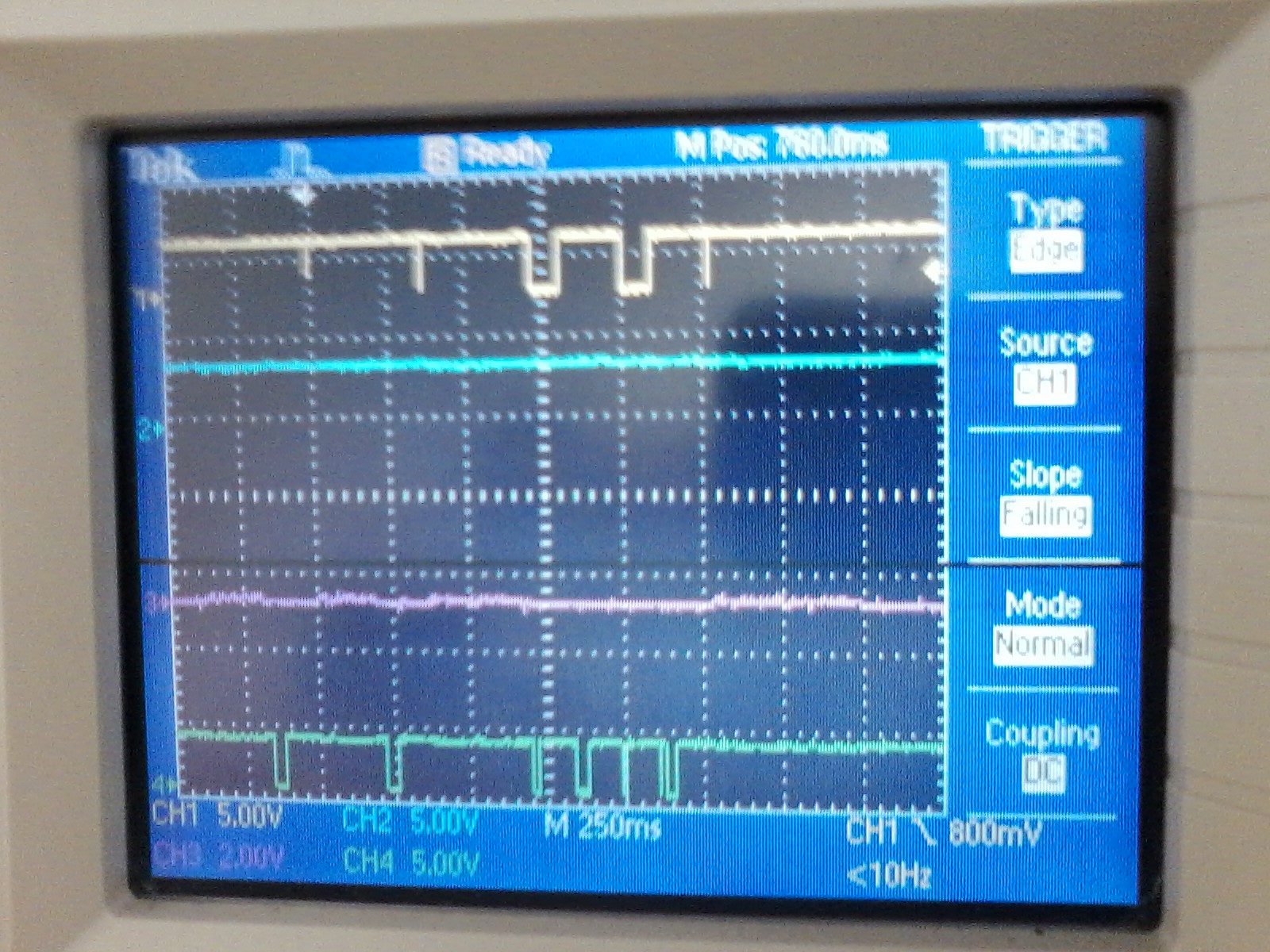
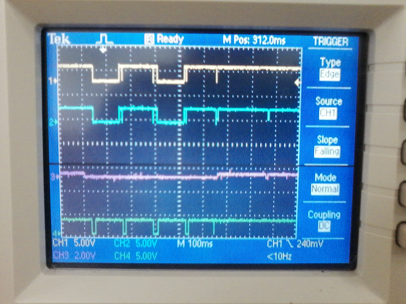
    Comm picture are as such. 

    CH1 - Yellow - TDO 

    CH2 - Blue - TDI

    CH3 - Purple - TMS

    CH4 - Green - TCK

    Now TMS looked very noisy so I zoomed in on the noise.

    And it was consistent.

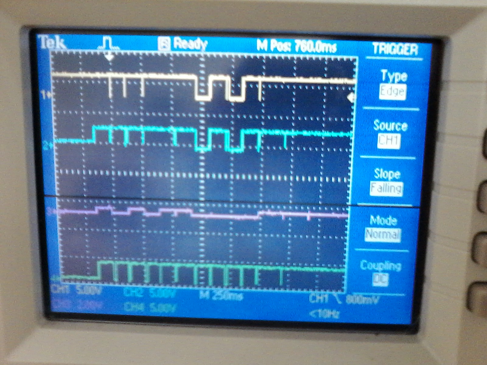
    And the programming sequence.

  • So continuing to bang my head against this problem I've tested the circuit again this morning.  The noise in TMS went away, but so did all signals.

    So I plug in the other programmer MSP-FET430UIF and got a different results.  Seems the TMS doesn't get driven high enough...

  • Hi Michael,

    What Vcc is your external power supply operating at? What happens when you try to power the MSP430 device through the FET (using JTAG pin 2 instead of 4)?

    Regards,
    Ryan
  • The system is powered by a 3.3V rail that I can see is 3.3. I will remove R23 from the system and solder a blue wire directly to pin 2 and try again and return with pictures.
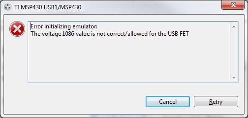
  • Using MSP-FET first leaving R23 installed and removing 3.3V rail regulator the voltage to the MSP430 was 1.08 V giving the following error upon any attempt to program it.

    Using the UIF same error occured.  Unknown device.  The rail voltage was 3.1V.  The O-Scope lite up as such...

  • Is there a 2-pin JTAG capable MSP with a simular pinout?

  • Any MSP430 device that is compatible with the MSP-TS430PM64 target board, in accordance with the MSP430 Hardware Tools User's Guide (SLAU278), should have a similar (but not exact) pinout. Do you not have any target boards, TI-provided or otherwise, to test with and confirm whether the 4-wire JTAG issues lies with the MSP430F167 custom board or the FET tools? I am trying to pull in a MSP-FET expert to comment on this matter but he is unfortunately not available this week.

    Regards,
    Ryan
  • I have a MSP-EXPCC430RF board from TI, but unfortunately it has the FET installed on the board called the Debug Interface (very clever of you guys).  I do have a Wizzi-Kit designed by Wizzi-Lab () using a 4-wire FET interface using the CC430F5137 we modeled our DTRA board design after.  It too is an unknown device to CCS with a known good firmware and known good development board.

    So to recap I have a new board design (611), a known good personal design (DTRA), and a development kit (Wizzi-Kit) all using 4-wire JTAG, all have unknown device to CCS.  I have an Olmiexino-5510 with a MSP430F5510 using 2-wire JTAG that both FETs can program (annoying right?).

    In the interest of saving time I have ordered another MSP-FET430UIF to see if it could be the problem.

  • It was the programming port. I purchased an MSP-FET340UIF and received it this morning. It work on the first try. Is the MSP-FET compatiable with 4-wire programming? Is it possible to exchange this MSP-FET if that is true? I'd like a second programmer for future developments.

    Mike
  • Hi Mike,

    The MSP-FET supports 4-wire programming. The error you mentioned before, where "The voltage 1086 value is not correct/allowed for the USB FET" is sometimes produced if the MSP-FET is oriented incorrectly. Have you confirmed that pin one of your JTAG header matches pin one of the MSP-FET device? You might try rotating the connection by 180 degrees to see if it produces any changes. Otherwise, you believe that the MSP-FET device you purchased was delivered already defective and has never worked?

    Regards,
    Ryan

**Attention** This is a public forum