This thread has been locked.

If you have a related question, please click the "Ask a related question" button in the top right corner. The newly created question will be automatically linked to this question.

Internal crystal oscillator failing in MSP430F5419A MCU

Other Parts Discussed in Thread: MSP430F5419A

Dear All,

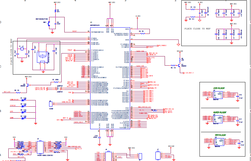
One of our customer is using MSP430F5419A for GPS/GSM based vehicle tracking.  whenever GSM/GPS burst is coming up, internal crystal oscillator in MSP430F5419A MCU stops working, In their application firmware they have added timer interrupt based LED blink for every 1 sec. Hence whenever the crystal fails the LED blink will stops. Due to this issue there is huge escalation has been raised from their customers. hence they have modfied schematics with some ESD protections , please advise how to resolve the issue, look forward for your support.

Aravind.

  • Let me guess: to save cost, they've put the GSM antenna right near the crystal?

    The MSP has the capability to report oscillator faults. It is not a good idea to ignore them.

    Anyway, show the PCB layout for both the MCU and the GSM signals.

  • Dear Sir,

    I have attahed scematics section for MCU & GSM/GPS, please check and do the needful.


    Aravind.

  • Problem as well can be caused by groud loop, insufficient power rail filtering/decoupling
  • Dear Ilmars sir,

    Please advise the changes that needs to be done/added in design to in-order to make internal crystal working continuousky even if GSM/GPS burst is coming.

    Please advise whether any other portion of schematics needs to be shared for further review.


    Aravind.

  • I did not ask for the schematics but for the PCB layout.
  • >Please advise the changes that needs to be done/added in design
    Schematics alone does not tell anything regarding groundloops nor power rail noise. First thing you shall do - thorough noise analysis of the circuit, compare devices that are suspect to problem with devices which are not, see how they supposedly differ. I would let engineer to solder 50ohm cable to power rail of msp430 as close as possible to chip and look at supply ripple during GSM burst using scope having 50ohm input. Put extra storage and decoupling capacitors, close to GSM power stages and any other hi-power consumer chips, do analysis and tests again. Add supply filter ferrite bead(s) before LDO and before decoupling caps of msp430 too. Also I would ask engineer to do PCB current density analysis. When it is clear that PCB routing is OK, then RF radiation analysis and experiments using additional shielding and/or even absorbers. When you find source of the problem - only then you think how to fix it.

    [edit] Stopped LED blink also could mean reset of the chip for some reason. You are advised to add some special LED blink pattern during init time, another pattern for oscillator fault lockup loop and so on -  so you clearly see exact state of the chip. Do you happen to use WDT with proper reset?

  • Dear Sir,

    sure these details are shared with customer. please fnd attahed gerebr for your reference and advise.

    Aravind.GERBER.rar

  • >please fnd attahed gerebr for your reference and advise.

    Well, how to say.. Unless you provide web-friendly picture with colored power rails and other high-current paths like RF feed, It (analysis of circuit and gerbers) is more or less out of scope of this "spare time forum"

**Attention** This is a public forum