This thread has been locked.

If you have a related question, please click the "Ask a related question" button in the top right corner. The newly created question will be automatically linked to this question.

How can i power with battery my MSP430F5529 ??

Other Parts Discussed in Thread: MSP430F5529, TPS2041B

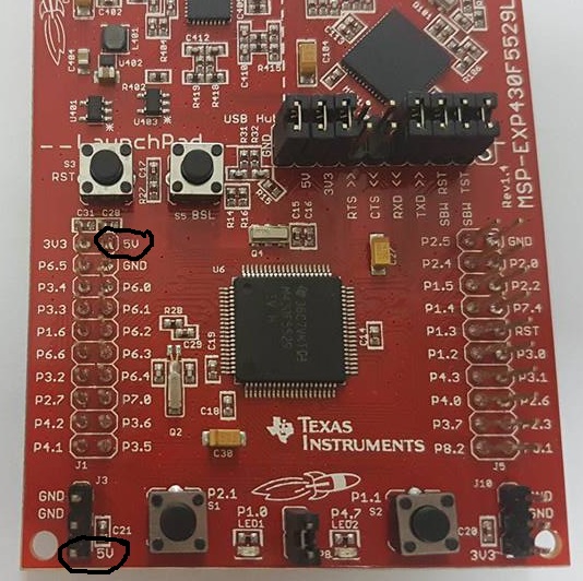
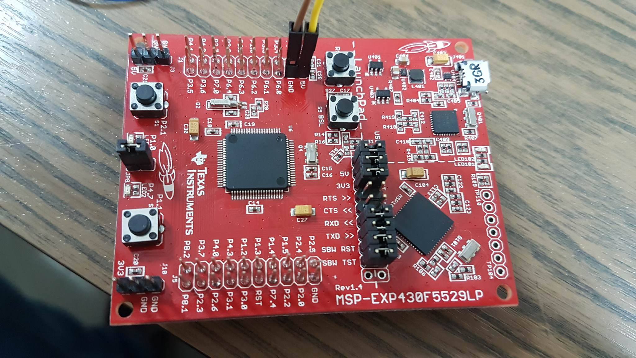
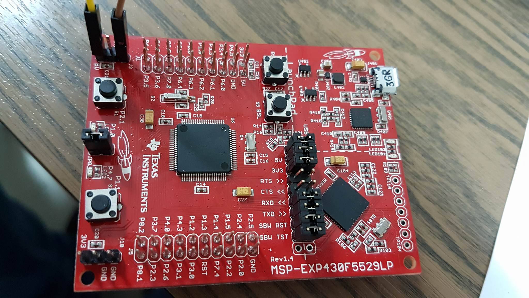
Hello. I have MSP430F5529 board. I want to use it for my 9 v dc motor application. For that i have to unplugged the usb and power my board with battery..I can use 2 series 1.5v batteries. But which pins should i use for power and ground? A pic of my board is below. Thanks in advance!

  • See section 2.4 of the LaunchPad User's Guide.
  • Dear Guru..

    I read it today many times..But i ve understood nothing! A diagram and differnt coloured lines..The answer must be so basic like "connect to pin .... and for ground connect the pin ..." Why everything should be complex?
  • 9V motor but 2V-3V battery connection?
    Is the 9V coming from a low esr battery,
    why not use a voltage regulator on this 9V to get it down to 5V
    and the Launchpad's 3.3V TPS62237 Step-Down Converter handles the rest
  • Thanks Tony.

    But i wonder that how i connect my 5 v to TPS62237? which pins are TPS62237 's input?
  • Anywhere you see 5V pin, as this comes from USB port normally and goes the boards 5Vbus and to the TPS62237

  • Tony thanks for your answers. I connected as you said (i attached a photo) but nothing changed..Why? My jumpers are connected as you see on the photo.

  • There appear to be four cables connected. What are those?
  • 5V pins and ground pins..i labeled on the picture.

  • But why are there two 5V cables and two ground cables?
  • Because one pin source did not work and i tried that way..But it did not work too..One pin source pictures are below..

  • Hi!

    You are talking about 3 different voltages:
    a) ~3V from two batteries in series (not enough to feed this voltage into the 5V pin)
    b) 5V from an external supply (OK to feed into the 5V pin)
    c) 9V from somewhere else (will damage the board if fed into the 5V pin)

    Are you feeding 5V into the board now?
    Did you first feed 9V into the 5V connection? I hope you didn't - the TPS62237 can only handle up to 7V.

    All 5V pins on the board, all 3V3 pins and all GND pins are connected, no need to power more than one. But if you feed in 5V to any of the appropriate pins, then the board should run when the 5V jumper between emulation and target side is closed.

    If you are not sure about the hardware connections of the board, have a look into the schematic that can be found in the hardware design files.

    Dennis

  • As you see on the picture i only sourced the 5V pins. Yes i sourced it with 5V dc supply but it doesnt work...No i only sourced it with 5V not 9V.
  • What does a multimeter say on the other 5V pin when you have your 5v source connected?
    Do you get a (around) 5V? if so what does a 3.3V pin reads?

  • It says 5V on the all 5V pins when i supply 5V pin on the left bottom corner but 3V3 pins give 0.6 volt.. So my emulator is break down??
  • Power it up with "normal" USB again and test,
    The data sheet does not say anything about the buck Converter getting its enable pin from a USB enumeration for example.
  • Have you tried looking at the schematics for the board? I have a feeling the answer is no, and I have a feeling you don't have any formal electronics training. Which is fine, but help us manage expectations and the correct level of hand-holding required here.
  • Yes Brain you have entrancing feelings! But i'm sorry Brian after that i used STM32f4 discovery board and this only take 5 seconds..After i had a problem on my Pololu motor driver and i wrote it on Pololu forum..and again i got my answers in 2 hours..But i could not get answers here TI forum days...Why?? Because my questions are too hard to answer right? I dont think so..Because you are here only waste your time..not to help..I will take a FORMAL electronics training Brian..It s for you..
  • mehmetserdarcelik said:
    But i could not get answers here TI forum days...Why??

    Why? Because these questions mostly get answered by non-TI people who are here in their spare time answering questions. There is no "service-level-agreement". And sometimes the people doing the helping cannot answer every question.

    mehmetserdarcelik said:
    Because you are here only waste your time..not to help

    Absolutely not. I made a suggestion, and asked for you to help me understand what level of detail you would need. I like to know my audience so I can give the appropriate level of detail. Detail that varies whether helping a relatively inexperienced hobbyist or a professional engineer with years of experience. 

    If you can post a system-level block diagram of what your power/motor/micro system is supposed to look like, then we can also give advice on other possible ways to hook the power in your system.

  • Yes you are right. If you dont want to help dont do it. But dont judge me or anyone. It is so obvious i said it too many times..I only want to supply my MSP board with 5V. Is it too hard to understand?? Board user guide page 21 gives a schematic like i said before but in this schematic i understand if i only supply 5V to any 5V pins. And i did it! But it did not work! I just want to blink the led that is on the board without usb power supply...And so i come here to get it. Is it obvious enough?
    By the way, if you show me this question is answered anywhere on this forum, i will apologize and leave here.
  • Your problem could be fact that you use v1.4 board which includes TPS2041B power switches. Perhaps Brian missed that and whole time analyzed wrong (rev >= 1.5) schematics.

    >By the way, if you show me this question is answered anywhere on this forum, i will apologize and leave here.

    It could be so that you can start apologise now. Indirect answer is in FAQ of Launchpad User's Guide:

    Q: I'm trying to power the LaunchPad from a USB power supply (not an actual USB host), and it is not working. Does the LaunchPad not support this?

    This problem is fixed in Rev1.5 and later LaunchPads. Unfortunately Rev1.4 does not. USB hubs typically shouldn't enable power to their downstream devices until the hubs themselves enumerate on the host, and that's what the TUSB2046 on the Rev1.4 F5529 LaunchPad does through the TPS2041B power switches. If the hub never enumerates, power is not provided to the target F5529. Because the downstream device is permanently attached in this application, the TPS2041B switches are not required by the USB specification. Rev1.5 and newer F5529 LaunchPads have these switches removed, to avoid this problem. Again, the benefit of the hub is single-cable development. Other power supplies can still be applied via the power header

  • Good catch!
  • Tell me Ilmars where did this answer on this forum before? I read User Guide of which TI GAVE ME!

    And inside the user guide...

    Why does TI DO that?? Do i need now buying a new version? Really it is so funny..I have two board of TI..MSP430 launchpad and MSP430F5529 launchpad board..And now for me both of them are garbage! Thanks for EXTRAORDINARY ENGINEERING TI AND PERFECT TI Forum wises!

  • mehmetserdarcelik said:
    Tell me Ilmars where did this answer on this forum before? I read User Guide of which TI GAVE ME!

    The mentioned question and answer is on page 53 of the document you made a screenshot of. The photo shows a Rev1.4 LaunchPad, but the text explains it. A lot of products are revised after some time - mostly to improve usability for you.

    mehmetserdarcelik said:
    Thanks for EXTRAORDINARY ENGINEERING TI AND PERFECT TI Forum wises!

    Understandable that you are not happy about the fact, but I would say there is no need to be that mad now.

    Think like an engineer and do a hack on the TPS2041B!

    Dennis

  • >Why does TI DO that??

    As FAQ of Users Guide clearly say - TI followed USB spec power management requirements. Later they think over because of unfortunate problems you experience.

    >Do i need now buying a new version?

    No. You shall look at rev 1.4 schematics and rev 1.5 schematics, compare power part. Think of simple hack - how to short mentioned power switch on rev 1.4 so it behaves as rev 1.5. In case you need help in this regard - feel free to kindly ask questions. Ranting and requesting ready to use solutions on golden plate usually does not increase your chances. Further reading

  • Hi mehmetserdarcelik,

    Please allow me to clarify a little bit of what happened with the power sequencing on the F5529LP, then I can make some suggestions for how to connect your different power rails.

    In the original release of the F5529LP, we (TI) made the decision to only enable the 3.3V converter when the UCB is enumerated (connected to a USB host).  The original thought here was that in all use cases, the LP would be connected to the pc via USB (for debugging), or would be powered externally through the 3.3V and 5V power headers at the bottom of the board.  After release, we realized there was significant demand for powering the LP through a USB power supply (that does NOT include a USB host), so we redesigned the board to accomodate this.  As Ilmars pointed out, unfortunately, you have an old version of the LP that does not support enabling the 3.3V converter when the USB is NOT enumerated.

    Now, this does not leave you completely high and dry.  If you want to power your LP from a non-USB Host source, you can do so through the 3.3V and 5V connectors at the bottom.  However, you need to disconnect the 3.3V and 5V jumpers between the emulator and the target side of the LP.  This will bypass all the power configurations in the emulator and let you power the LP device directly form an external source.

    For your application, you can power the 3.3V (VCC) rail with 3V from batteries to power up the LP device.  I don't think you need the 5V rail (unless I missed something somewhere), so you can ignore this.  Your 9V rail for your motors can share the ground with your batteries if you would like, although I would recommend isolating these rails if possible to prevent injecting noise from the motor on your LP power rails.  As mentioned above, just disconnect the 3.3V and 5V jumpers on the emulator/target header, and this configuration should work fine.  You can still debug the application using the emulator as long as the ground jumper is still connected.  If you don't want to debug the application, I recommend removing all the jumpers on that header to prevent undesired voltages on those pins.  Particularly important are the RST and TEST lines (for SBW JTAG communication), as these can potentially hold the device in reset.

    I apologize for the confusion between the LaunchPad revisions, but it is an unfortunate side effect of the product evolution process.  Hopefully the above, combined with the support of some of the other forum members can help you get your demo up and running.

    Mike

  • > If you want to power your LP from a non-USB Host source, you can do so through the 3.3V and 5V connectors at the bottom. However, you need to disconnect the 3.3V and 5V jumpers between the emulator and the target side of the LP

    I doubt that removing 3.3v and 5v jumpers will do any good to power LP through 5V connector at the bottom. Unfortunately I cannot doublecheck because TI quickly removes old versions of documents

    Mike, could you point out where we can download rev 1.4 LP documentation (Users Guide) including schematics? Note that current UG does not show schematics of rev 1.4

    [edit] Just tested rev 1.4. It does not work from 5V as Mike say. Unfortunately have no schematics, so don't know how to fix it.

  • Was looking for the older design files as well :/
  • Ilmars, Dennis,

    I am unsure if the old versions are available externally. I am checking into this and will let you know what I find.

    My point about removing the 3.3V and 5V jumpers between the emulator (eZFET) and the target sides of the LaunchPad was to separate out all the power management on the eZFET side from the external power connections that will be made to the board. Without removing these jumpers, you will be back-feeding the 3.3V converter if you apply a voltage to VCC. This also will power the eZFET, which could lead to issues where the emulator holds the device in reset or something because it is not receiving instructions from the PC over USB telling the eZFET what to do. While the 5V does not have a voltage converter, it is connected directly to the USB plug, which means if you plug USB in with an external 5V rail on the device side, you could potentially cause issues there.

    Removing the 3.3V and 5V jumpers makes those rails on the device side sourceless on the board. Now you are safe to connect external power. The benefit of doing this is that you can STILL use the eZFET through the USB to the PC to interface the F5529 (either through JTAG or the back channel UART), while keeping the external power source.

    Mike
  • > Without removing these jumpers, you will be back-feeding the 3.3V converter if you apply a voltage to VCC
    All the time we are talking about 5V connector, not 3.3V !!

    >if you plug USB in with an external 5V rail on the device side
    5V connector _without_ USB plugged in

  • Ilmars,

    The 3.3V rail is generated in the eZFET side from the 5V rail. So if the 5V jumper is in place and 5V is applied (either through USB or externally), it will generate a 3.3V rail for VCC (if a USB host is present). If you already have an external source on the 3.3V/VCC rail, this would not be good. In the original post, mehmetserdarcelik mentioned he wanted to connect 3.0V from batteries to VCC. This is why I brought up this point.

    I brought up the 5V _with_ the USB plugged in to explain the revision change from 1.4 to 1.5, and why those changes were necessary. On rev1.4 boards, applying 5V externally (with the 5V jumper between the eZFET and target sides in place) is effectively the same as connecting the USB to a wall charger that is NOT a USB host. Since the rev1.4 board requires a USB host to enumerate the eZFET before it will enable the 3.3V converter, it does not matter where the 5V comes from, it will not enable the 3.3V converter if there is no USB Host present.

    Mike
  • > Since the rev1.4 board requires a USB host to enumerate the eZFET before it will enable the 3.3V converter, it does not matter where the 5V comes from, it will not enable the 3.3V converter if there is no USB Host present.

    Ok. Now it is definite answer. On the other hand what is suggested solution for rev1.4 owners willing to do some soldering to fix the problem? Same as I did - remove power switches U401 and U403, solder "always on" jumper wires?

    And where's schematics of rev1.4 LP?

  • Ilmars,

    The hardware solution would be to bypass the enable single from the eZFET controller and have the 3.3V converter always on. I don't have the schematics in front of me to give specific changes, but this is effectively what you are trying to do.

    The rev1.4 schematics are not currently available online. I am working the team to make these available, but this will likely take a few days.

    Mike
  • The rev1.4 schematics are not currently available online.

    Actually, they are.

  • what is suggested solution for rev1.4 owners willing to do some soldering to fix the problem?
    1. Remove U401 and U403, and connect the pads for pins 5 and 1.

    2. Alternatively, disconnect the enable signals (pin 3) from the hub's PWRON signal, and connect them to GND instead.

    MSP-EXP430F5520LP 1.4 power switches

  • Good old Leo Bosch could help out again!

**Attention** This is a public forum