Hi,
I'm trying to optimize CC430 current consumption and was trying to use LMP3. The actual application utilises ADC, UART and RF part. I have decided to first optimize the microcontroller part and then add RF part. For sampling ADC, i use a timer A0 which triggers ADC every one millisecond so that the sampling rate is 1kHz. The following code worked well when I tried for the first time using LPM3.
int main(void)
{
    WDTCTL = WDTPW | WDTHOLD;	// Stop watchdog timer
    //port mapping SMCLK to pin 1.2 to monitor SMCLK
    PMAPPWD = 0x02D52;                        // Get write-access to port mapping regs
    P1MAP2 = PM_SMCLK;                      // Map UCA0RXD output to P1.5
    PMAPPWD = 0;                              // Lock port
    P1SEL |= BIT2;
    P1DIR |= BIT2;

    P1DIR |= BIT3;                            // P1.3 to monitor the interrupt event
    P1OUT &= ~BIT3;

    P3DIR |= BIT7;                           //for LED blinking
    P3OUT &= ~BIT7;


    ADC_trigger_timer();                 //Configures the timer
    __bis_SR_register(GIE+LPM3_bits);    //Enable GIE and LPM3 mpde

    P3OUT|= BIT7;                       // BLINK LED
    __delay_cycles(10);
    P3OUT&= ~BIT7;
    __delay_cycles(10);
 }

void ADC_trigger_timer()    // TIMER CONFIGURATION
{

	  TA1CCTL0 = CCIE;                          // CCR0 interrupt enabled
	  TA1CCR0 = 8;                              // Count value
	  TA1CTL = TASSEL_1 + MC_1 + TACLR + ID_2;         // ACLK, upmode, clear TAR, divide by 4
}

#pragma vector=TIMER1_A0_VECTOR      //TIMER ISR
__interrupt void TIMER1_A0_ISR(void)
{
	  P1OUT ^= BIT3;                            // Toggle P1.3 - expected to get a square waveform with bit period 1 ms
       __bic_SR_register_on_exit(LPM3_bits);

}
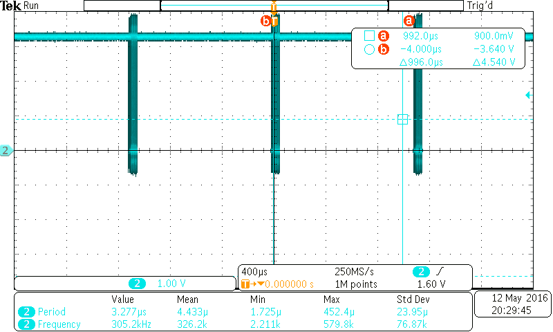
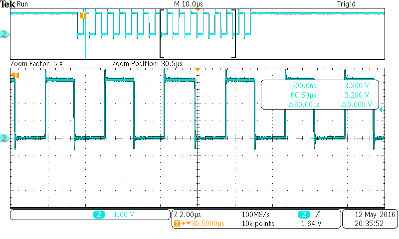
Can you please explain what does __bis_SR_register_on_exit(LPM3_bits) do? Upon experimentation, I came to know that the lines of code after __bis_SR_register_on_exit(LPM3_bits) doesn't get executed if I don't add this line at the end of ISR. One more thing I found is that if I keep this line __bic_SR_register_on_exit(LPM3_bits); at the end of ISR. I can observe SMCLK running continuously whereas executing the code without this line shows the periodic operation of SMCLK. In my application, I want to:
1) Enter LPM3 when __bis_SR_register(GIE+LPM3_bits) is executed
2) There is a timer interrupt which occurs once in every 1 ms. Once the interrupt is called, mcu exits LPM, enters the ISR. At the end of ISR, I want the process to flow back to the main loop to execute some peripheral processes.
3)After executing the lines, it has to again go back to LPM3 and wait for the next interrupt to occur.
Someone help me in implementing such application.I have attached the screen shots of SMCLK when the exit statement is not used at the end of ISR. But this doesn't flow back to the main loop.
SMCLK at 1.035 MHz


