Hello!
I'm trying to invoke BSL using 2 GPIOs of other MSP. But, after doing so, I'm not getting any response from MSP. The steps I followed are:
1. Flashed LED Toggle code on MSP that's to be upgraded.
2. Sent toggling sequence from other MSP. LEDs stopped toggling.
3. Sent Tx_BSL_CMD and didn't get any response back.
When forced MSP to enter BSL using software, I'm getting response back. So, there's some problem with the entry sequence.
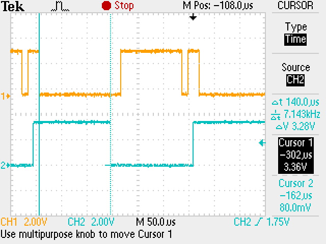
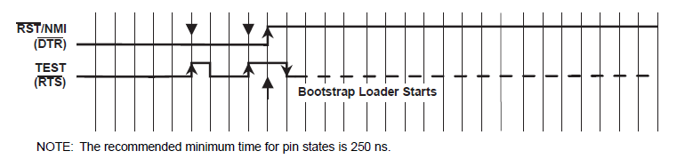
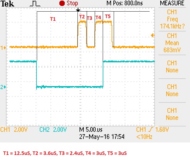
Sequence:
Am I missing something obvious here? Please let me know.
Teja