This thread has been locked.

If you have a related question, please click the "Ask a related question" button in the top right corner. The newly created question will be automatically linked to this question.

EVM430-F6779 Calibration

I am trying to properly calibrate the EVM430-F6779 power meter. All I have is some multimeters and a resistive and reactive load bank. The current calibration seems to change when switching between inductive and capacitive loads. How should I go about calibrating the device with the equipment I have? Also, in the documentation, what is referring to by the reference meter when calculating active and reactive power?

Thank You

  • The only reason I can think of for the current calibration appearing to change between inductive and capacitive loads is that the loads introduce a lot of harmonics. The different frequency responses of the reference current meter and the EVM can cause significant differences in the readings in those circumstances.

    Power meters are usually calibrated against a reference power meter. You can calibrate the EVM's voltage scaling easily, by comparing its results against an accurate AC voltmeter. If you feed a load through the EVM and an accurate AC current meter you can easily calibrate the current scaling. If these two calibrations are accurate the power scaling should also be accurate. The last calibration requirement is more difficult to perform without a reference power meter. The phase relationship between the voltage and current signals needs to be adjusted, so they are exactly time coincident. This is usually done using a reference power meter and a load with a poor power factor. At poor power factors the measured power is very sensitive to small phase errors between the voltage and current signals. It is then easy to adjust their phase relationship until the reference meter and the EVM agree on the power reading. This adjustment is to correct for phase errors outside the metering MCU. Everything in the MCU is digitally timed, and very predictable. However, the analogue filters feeding into the ADC pins have component tolerances, and some sensors, such as CTs, may introduce substantial phase shifts.
  • I am able to calibrate the meter fairly well with this method except my reactive power is still substantially off from my calculated value for reactive loads. Any more advice?
  • Alden Coleman, colleague of Kyle Mann here. 

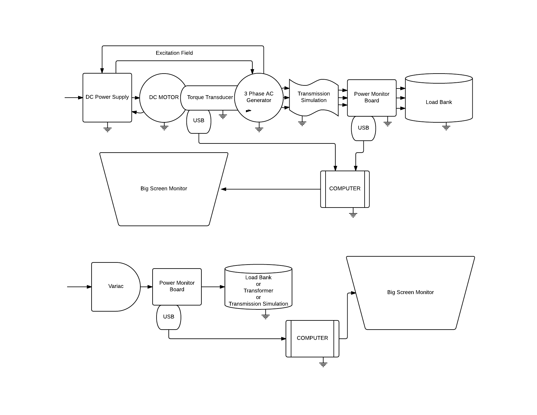
    Here is a block diagram of our intended setup: 

    We intend to use to the TI MSP430 in our power laboratory at the University of Tulsa. We want to provide an interactive, hands-on lab with real and reactive power. Our current lab only uses handheld meters for readings. 

    We do not have access to a reference meter at this time. I understand that harmonics may interfere with the current readings. 

    Support thread: e2e.ti.com/.../518144 is related to this issue. At one point we added a very high calibration factor to the software. This caused B phase voltage to read high for any value. When we tried to undo what we did, it set the calibration factor to zero. 

    Thank you for your assistance with our issue.

  • Near unity power factor the active power reading is fairly insensitive to phase errors, but the reactive reading is very sensitive. As the power factor drops the active power becomes more sensitive to phase errors and the reactive power becomes less sensitive. By zero power factor the sensitivities of the active and reactive power completely reverse. If you are testing close to unity power factor and have a small phase shift between the voltage and current signals you might see great results for active power measurement, but very poor accuracy in the reactive measurement.

  • Yes that does seem consistent for our results we get discrepancies in current measurement when we have a purely reactive load but not for resistive. How would you recommend going about calibration for both loads to achieve maximum accuracy for both load extremes (resistive, 0.5 lagging, 0.5 leading)?

  • Few loads are purely resistive or purely reactive. A water heater element is probably the closest thing to a purely resistive load that is easy to find. The strong cooling effect of the water prevents the temperature oscillating too much through the 50/60Hz cycles. By comparison, an incandescent light bulb can give you about 15-20% THD and some phase shift, due to the large oscillations of temperature, and therefore resistance, in the filament.

    If you have a purely resistive load there is a simple trick you can use, but it requires some alteration to the code...

    Buffer the voltage signal for enough samples to delay it by about 60 degrees. Use the exact mains frequency and sampling rate to work out the exact phase delay you have created. From this, work out the exact power factor this delay represents. It should be something like 0.5PF. In this area power measurements are very sensitive to small phase errors. Now make the software calculate power from the delayed voltage signal and the undelayed current signal, just as it calculates power from the undelayed voltage signal and the undelayed current signal.

    The power calculated from the undelayed signals should be a good estimate of the correct power into your resistive load, even if there is a small phase offset between the undelayed voltage and current signals. It takes a 2.5 degree phase error to cause just 0.1% of error in the measured power at unity power factor. Work out what power reading you would expect from the delayed voltage and undelayed current signals, using the effective power factor you worked out earlier. Now compare this with what you actually get. Even small phase errors cause a substantial difference between these numbers. If you adjust the phase until they match you should have a meter that is accurately calibrated for phase.

    Our metrology software used to incorporate this technique, so we could calibrate meters with a single measurement on a test set. However, we found that in practice none of the test sets we tried could be relied upon to consistently stabilise their phase to the required accuracy, so we took it out.

**Attention** This is a public forum