This thread has been locked.

If you have a related question, please click the "Ask a related question" button in the top right corner. The newly created question will be automatically linked to this question.

Executing interrupts during Flash read/write

Other Parts Discussed in Thread: MSP430F5659, MSP430F6659, MSP-FET, MSP430F5436, MSP430F5438, MSP430F5438A, MSP430F5529

I need some help with this, maybe someone already had the same problem and can give me a push in the right direction.

We need to erase and write flash while executing interrups routines.

The application has a particular function that communicates with the exterior at 1.5kHz. The erase times of the flash make it imposible to wait for the flash to finish so the code has to be in RAM and keep running. The periodic function is called by the timer interrupt and it has its own internal timeouts so interrupts are a must.

We moved the code to RAM to allow execution during flash erase, and it works fine, but interrupts stopped being serviced.

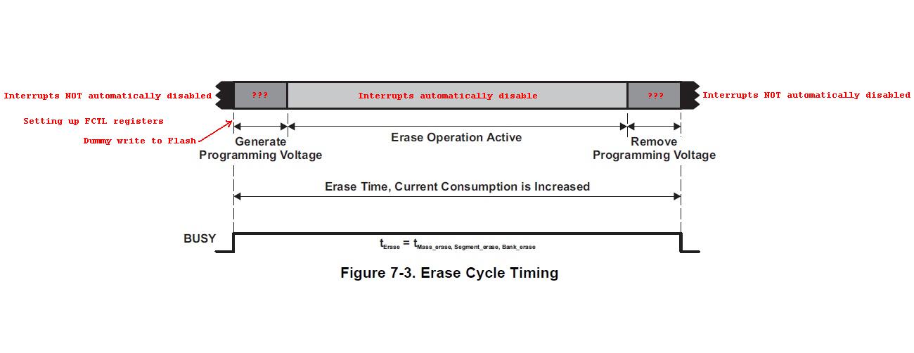
We use a MSP430F5659. Looking at the datasheet (slau308 section 7.7.3) we found that "Interrupts are automatically disabled during any flash operation."

Is there a way to keep interrupts running while Flash is being erased/written?

Moving the interrupt vector to RAM should do it, but is it possible/safe to enable interrupts during flash operations?

I did look around and couldn't find anything on this topic, only a hint that it shoould be posible in this thread https://e2e.ti.com/support/microcontrollers/msp430/f/166/t/18998 but it's not even clear if it will work.

Any help is appreciated

  • Agustin Villavedra said:
    Moving the interrupt vector to RAM should do it, but is it possible/safe to enable interrupts during flash operations?

    I haven't found anything which says that it is possible/safe to enable RAM based interrupts during flash operations. The thread https://e2e.ti.com/support/microcontrollers/msp430/f/166/p/408832/1450548 suggests polling the interrupt flags.

  • I think it is possible to enable interrupts during flash operations if (a) the interrupt vectors are in RAM, (b) the ISRs are also in RAM, and (c) the ISRs do not access Flash ever. Essentially, this is similar to what Chester suggested, but you are polling the Flash operation instead.
    I am not sure how safe this is.
  • Thank you both, according to that thread it "should" be possible, and we will try it. We cannot poll IFGs as timing is important down to microseconds and polling times would be excesive. As old_cow states only RAM access for ISR excecution.

    The safe part still remains to be seen.... if anyone finds any information on this it would be of great help.
  • Maybe TI USB BSL source code can help you. It will download last (new) BSL version to RAM and execute it (flash erase / write / verify) from there. It is using (USB) interrupts.

  • zrno soli said:
    It is using (USB) interrupts.

    I looked at the 5xx_6xx_BSL_Source\Peripheral_Interfaces\USB\Proj_Settings.h in MSP430BSL_1_00_11_00 and as far as I could tell it is using polling rather than interrupts.

    There is the following definition:

    #define _NO_ISR         // Do not use USB interrupt, handles it by polling
    

    And the file header comments contain:

    |  R.Stolyar    2009/03/12   Change from interrupt handling to polling        |
    

    Is there another USB BSL version which does use interrupts?

  • So we tried enabling interrupts after starting the Flash erase and it's NOT servicing interrupts. Will check again to see if we are not referencing flash at all but apparently not.
    Next step is making a much simpler code to make sure it's not something else, but so far it seems it cannot be done.

    Could interrupts be disabled at hardware level? Is there something at lower level than GIE?


    I'll look into the BSL code, thanks zrno and Chester for that.

    Will update if we find anything new.
  • According to both the datasheet (which you quoted) and to that thread, interrupts are disabled at the hardware level.

    You cannot use interrupts. You must use polling.

  • Clemens is correct. For some reason, TI decided that Interrupts are "automatically disabled" when Flash operation is on. I was wrong. I missed that and could not figure out why such a feature is needed.
  • Agustin Villavedra said:
    Moving the interrupt vector to RAM should do it, but is it possible/safe to enable interrupts during flash operations?

    As a learning exercise created a test program for a MSP430F6659 with the intent of:

    1. Using a timer ISR in RAM, with the ISR vectors also in RAM, to increment a counter every 500 microseconds.
    2. Performing an erase, program and verification of flash with the code running in RAM.

    Due to the documentation saying "Interrupts are automatically disabled during any flash operation" the expected result was that comparing the count of how many times the timer ISR was handled .vs. the elapsed time of the flash operation would show that the timer ISR was not occurring as often as expected. However, the actual result was that the program crashed, with the program counter ending up with the invalid value of 0x4. The crash is occurring during the programming of flash, and from run-to-run the how far though the flash programming before the crash occurs varies. i.e. appears timing sensitive.

    If the program is changed to place all of the program in flash, rather than RAM, then the program completes and the timer ISR is only executed for approx 42% of the expected iterations. i.e. shows interrupts are being blocked during flash operations.

    Not sure if the crashes occur due to an error in the program, or the act of attempting to service interrupts from RAM during flash operations has highlighted undefined behavior / an errata.

    The test program is attached. The value of the predefined symbol USE_RAMFUNCS on the compiler and linker specifies if the timer ISR and flash programming code are in RAM (USE_RAMFUNCS=1) or flash (USE_RAMFUNCS=0).

    Must admit that is not fully commented.

    MSP430F6659_isr_during_flash_ops.zip

  • It might be a good idea to try a test program that uses RAM-based interrupt vectors (without flashing) first.
  • You can arrange your code timing, by number of CPU cycles, outside an inside of interrupt function. Each 5xx device has different (hardwired) flash write timing, but some constant delays can be used inside block write to cover all devices, without testing BUSY / WAIT flags. Calling of interrupt function can be placed over the code on each 500 microseconds point (calculated by CPU cycles).

  • I have a code that works entirely from RAM and interrupts are not serviced.
    In conclusion it cannot be done, as you pointed out.

    We will have to find a way to work around this... maybe erasing Flash at moments with no timing restrictions... or using external memory... or using only RAM... we'll see.

    Thank you all for the help!
  • Clemens Ladisch said:
    It might be a good idea to try a test program that uses RAM-based interrupt vectors (without flashing) first.

    The previous description of my test program was vague. The program does the following:

    1. Place a timer interrupt handler in RAM using the TI compiler / linker support for RAM functions.
    2. Enable DMA which is triggered by a timer to perform a regular transfer from a test pattern in RAM to P1OUT.
    3. Copy the interrupt vectors from flash to RAM and set the SYSRIVECT bit to remap the interrupt vectors to RAM.
    4. Enable the timer interrupt.
    5. Make the CPU wait in a loop for several tens of seconds, to check that the RAM based timer interrupt is handled the expected number of times.
    6. Using code placed in RAM erase the FLASH2 sectors one at a time.
    7. Using code placed in RAM program the FLASH2 sectors with a test pattern, one sector at a time.
    8. Using code placed in RAM verify the test pattern which has been written to FLASH2.

    The crash was only observed during step 7, which indicates the RAM-base interrupt vector had been working successfully up until the flash programming was in-progress. The number of sectors which had been programmed before the crash varied from run-to-run, for reasons I didn't understand.

    Therefore, think the RAM-based interrupt vectors by themselves are OK.

  • Chester Gillon said:
    The crash was only observed during step 7, which indicates the RAM-base interrupt vector had been working successfully up until the flash programming was in-progress.

    When the program was suspended after a crash, the PC was an invalid value of 0x4.

    Using CCS 6.1.3 a breakpoint was set on the PC being written with an invalid value (less than the RAM start address since code has been placed in RAM), with an action to Halt and Trigger Storage:

    The MSP430 State Storage was configured to "Start immediately and Stop on Trigger" and to Filter on "All Cycles", to capture the internal bus activity leading up to the breakpoint when an invalid PC value was set. The MSP430 Trace storage prior to the PC being set to the invalid value of zero are:

    The last executed instruction shown in the Trace is RETI, at address 0x299c which is the expected timer A1 interrupt handler in RAM:

     58     {
            timer_a1_handler():
    002986:   140F                PUSHM.A #1,R15
     59         switch (TA1IV)
    002988:   421F 03AE           MOV.W   &Timer1_A3_TA1IV,R15
    00298c:   803F 000E           SUB.W   #0x000e,R15
    002990:   2004                JNE     ($C$L1)
     62             tick_count++;
    002992:   5392 26B4           INC.W   &tick_count
    002996:   6382 26B6           ADC.W   &0x26b6
     65     }
            $C$L1:
    00299a:   160F                POPM.A  #1,R15
    00299c:   1300                RETI    

    The PC value for the return from the interrupt is read from the stack at words 0x6332 and 0x6330. The return address is shown as zero, which explains why the PC gets set to zero. i.e. the RETI appears to be caused the PC for the main context to be set to zero leading to a crash.

    A Watchpoint with Data was then used to halt when a value of zero is written to the stack address from which RETI reads from. The Trace was:

    The address of the last instruction executed is 0x288A which is the expected function in RAM which is performing writes to flash. The 6th line of the trace is reading the RAM address of the timer_a1_handler from the RAM based vector table. The 7th line in the trace is the least significant 16-bits of the PC being pushed onto the stack, which is the return address used by the RETI instruction. The 8th line in the trace is the most significant 8 bits of the PC and the SR being pushed onto the stack. i.e. the trace appears to show that when the interrupt is detected an incorrect PC value of zero is pushed onto the stack. This looks to be a CPU errata / undefined behavior issue rather than a software bug.

    The program, attempting to execute timer interrupts in RAM while programming flash is using a MSP430F6659 Rev A device in a MSP-TS430PZ100USB target board with a MSP-FET. Will attempt to re-create the failure in a different type of device which allows a RAM based interrupt vector table.

  • I excavated an old skeleton, the MSP430F5436 (none-A), just to see that the "founding fathers" meant to make it possible to erase/write to Flash while at the same time running code with interrupt enabled as long as all the code and the interrupt vectors are in RAM.

    With a very simple test program, I can prove beyond any doubt that this can be done with F5436. Here is my test code. It is without any of the usual hoopla but somewhat unorthodox.

    #include <msp430f5436.h>
            org     0xFFFE                  ;RESET vector in FLASH
            dw      main
    
            org     0x1C00                  ;low end of RAM
    main:
            mov     #0x5C00-0x80,SP         ;high end of RAM, save 128 bytes for interrupt vectors
            mov     #WDTPW|WDTHOLD,&WDTCTL  ;here's code in RAM
            mov     #SYSRIVECT,&SYSCTL
            mov.b   #0,&P1OUT
            mov.b   #BIT0,&P1DIR            ;LED is off
    
            mov     #1048-1,&TA0CCR0         ;1 msec @ SMCLK=1.048 MHz
            mov     #CCIE,&TA0CCTL0         ;almost ready to go
    
            bis     #GIE,SR
    
    L1:     BIT     #BUSY,&FCTL3            ;Test BUSY -- just in case
            JNZ     L1                      ;Loop while busy
            MOV     #FWPW,&FCTL3            ;Clear LOCK
            MOV     #FWPW+MERAS+ERASE,&FCTL1;enable mass erase
    
            mov     #TASSEL1|MC0,&TA0CTL    ;start Timer
            
            CLR     &0FC10h                 ;Dummy write
    L2:     BIT     #BUSY,&FCTL3            ;Test BUSY
            JNZ     L2                      ;Loop while busy
            MOV     #FWPW+LOCK,&FCTL3       ;Done, set LOCK
    
            mov     #0,&TA0CTL              ;stop Timer
            bic.b   #BIT0,&P1OUT            ;LED off
    
            mov     #0,R15
    wait:   addx.a  #1,R15                  ;wait a couple of secoons
            jnz     wait
    
            jmp     main                    ;start all over again
    
    ta0_a0_isr:
            xor.b   #0x01,&P1OUT
            reti
    
            org     0x5BEC                  ;interrupt vector
            dw      ta0_a0_isr
    
            org     0x5BFE                  ;RESET vector
            dw      main
    
            org     0x5C00                  ;first word in Flash
            dw      0x1234
    
            org     0x35BFE                 ;last word in Flash
            dw      0x5678
    
            end

    The LED at P1.0 flashes briefly every few seconds. Using a scope, I can see that the LED-flash consists of 13 pulse with 1 ms duration and 1 ms gap in-between – very consistent with the expected mass erasure time.

  • old_cow_yellow said:
    I excavated an old skeleton, the MSP430F5436 (none-A), just to see that the "founding fathers" meant to make it possible to erase/write to Flash while at the same time running code with interrupt enabled as long as all the code and the interrupt vectors are in RAM.

    With a very simple test program, I can prove beyond any doubt that this can be done with F5436.

    Thank you for the test case.

    I have modified my test program to run on a sample of MSP430F5xx and MSP430F6xx devices. The test setup is:

    a) Configure MCLK at 16MHz, with the DCO clock FLL reference set to a 32768 Hz crystal on XT1.

    b) Configure SMLCK at 1MHz, by diving the DCO clock, to give timers a microsecond resolution.

    c) Set timer A1 to generate an interrupt every 25 microseconds. The timer A1 interrupt handler simply increments a 32-bit tick count. The timer A1 interrupt handler and the interrupt vectors are placed in RAM. The timer A1 interrupt period of 25 microseconds has set to a value smaller than the minimum flash byte or word program time of 37 microseconds.

    d) Create a free running 32-bit hardware timer, with the least significant 16-bits from the timer A0 count and the most significant 16-bits from the DMA transfer count. The DMA is set to transfer one byte from P1IN to memory, where the DMA trigger is set to the compare output of timer A0 causing the DMA0SZ register to decrement by one when the timer A0 count rolls-over.

    e) Make the program delay for ~40 seconds with __delay_cycles(), to check that the 32-bit hardware timer and timer A1 interrupt tick count are advancing at the expected rate when no flash operations are in progress.

    f) Erase all flash sectors at addresses >= 0x10000 one at a time, with all flash erasure code in RAM. The change in the 32-bit hardware timer and timer A1 interrupt tick count are reported to see if the timer A1 interrupt handler is being blocked by flash erasure.

    g) Program all flash sectors at addresses >= 0x10000, with all flash programming code in RAM. The change in the 32-bit hardware timer and timer A1 interrupt tick count are reported to see if the timer A1 interrupt handler is being blocked by flash programming.

    h) Verify the contents of the programmed flash sectors.

    1) The test results for a MSP430F5438 Rev L device are:

    [Sun Jul 10 16:23:05] Starting 40 second delay for sanity check of timers
    [Sun Jul 10 16:23:49] Delay took 43690762 microseconds (start=2860, stop=43693622) and 1747631 ticks (start=115, stop=1747746)
    [Sun Jul 10 16:23:49] Starting flash erase of 430 sectors with timer ISR and flash programming code in RAM
    [Sun Jul 10 16:24:02] Flash erase complete in 11728384 microseconds (start=43697908, stop=55426292) and 469135 ticks (start=1747917, stop=2217052)
    [Sun Jul 10 16:24:02] Starting flash program of 430 sectors with timer ISR and flash programming code in RAM
    [Sun Jul 10 16:24:11] Flash program complete in 8256010 microseconds (start=55431013, stop=63687023) and 329380 ticks (start=2217242, stop=2546622)
    [Sun Jul 10 16:24:11] Starting flash verify of 430 sectors
    [Sun Jul 10 16:24:11] Flash verify complete in 106499 microseconds (start=63691023, stop=63797522) and 4260 ticks (start=2546782, stop=2551042)

    During the delay loop, the 1747631 interrupt ticks at a 25 us period = 43690775 us which is within one tick period of the elapsed 43690762 us measured by the 32-bit timer. This demonstrates the timer and interrupt tick count are advancing at the expected rate.

    [While the __delay_cycles() aims for a 40000000 microsecond delay the actual delay is longer due to an interrupt every 25 microseconds]

    During the flash erase, the 469135 interrupt ticks at a 25 us period = 11728375 us which is within one tick period of the elapsed 11728384 us measured by the 32-bit timer. Therefore, the timer interrupt in RAM continues to be handled at the expected rate while the flash erasure code is running in RAM.

    During the flash programming, the 329380 interrupt ticks at a 25 us period = 8234500 which is ~860 ticks less that the elapsed 8256010 us measured by the 32-bit timer. Therefore, with the flash programming code running in RAM there is some timing "anomaly" since the tick count is ~0.26% less than expected.

    2) The results for a MSP430F5438A Rev D device are:

    [Sun Jul 10 16:30:29] Starting 40 second delay for sanity check of timers
    [Sun Jul 10 16:31:13] Delay took 43690761 microseconds (start=2861, stop=43693622) and 1747631 ticks (start=115, stop=1747746)
    [Sun Jul 10 16:31:13] Starting flash erase of 430 sectors with timer ISR and flash programming code in RAM
    [Sun Jul 10 16:31:25] Flash erase complete in 11124377 microseconds (start=43697909, stop=54822286) and 576 ticks (start=1747917, stop=1748493)
    [Sun Jul 10 16:31:25] Starting flash program of 430 sectors with timer ISR and flash programming code in RAM
    [Sun Jul 10 16:31:33] Flash program complete in 7974256 microseconds (start=54826930, stop=62801186) and 121845 ticks (start=1748679, stop=1870524)
    [Sun Jul 10 16:31:33] Starting flash verify of 430 sectors
    [Sun Jul 10 16:31:33] Flash verify complete in 106499 microseconds (start=62805185, stop=62911684) and 4260 ticks (start=1870684, stop=1874944)

    During the delay loop, the results are the same as for the MSP430F5438 device.

    During the flash erase the 576 interrupt ticks at a 25 us period = 14400 us which is only 0.13% of the elapsed duration of 11124377 us measured by the 32-bit timer. Therefore, the timer interrupt in RAM is not serviced at the expected rate when the flash erasure code is running in RAM.

    During the flash programming the 121845 interrupt ticks at a 25 us period = 3046125 which is only 38% of the elapsed duration of 7974256 us as measured by the 32-bit timer. Therefore, the timer interrupt in RAM is not serviced at the expected rate when the flash programming. code is running in RAM.

    3) The results for a MSP430F5529 Rev H device:

    [Sun Jul 10 16:36:27] Starting 40 second delay for sanity check of timers
    [Sun Jul 10 16:37:11] Delay took 43690762 microseconds (start=2860, stop=43693622) and 1747631 ticks (start=115, stop=1747746)
    [Sun Jul 10 16:37:11] Starting flash erase of 162 sectors with timer ISR and flash programming code in RAM
    [Sun Jul 10 16:37:15] Flash erase complete in 4215862 microseconds (start=43697907, stop=47913769) and 215 ticks (start=1747917, stop=1748132)
    [Sun Jul 10 16:37:15] Starting flash program of 162 sectors with timer ISR and flash programming code in RAM
    [Sun Jul 10 16:37:18] Flash program complete in 3032836 microseconds (start=47918371, stop=50951207) and 51903 ticks (start=1748316, stop=1800219)
    [Sun Jul 10 16:37:19] Starting flash verify of 162 sectors
    [Sun Jul 10 16:37:19] Flash verify complete in 40130 microseconds (start=50955150, stop=50995280) and 1605 ticks (start=1800377, stop=1801982)

    During the delay loop, the results are the same as for the MSP430F5438 device.

    During the flash erase the 215 interrupt ticks at a 25 us period = 5375 us which is only 0.13% of the elapsed duration of 4215862 us measured by the 32-bit timer. Therefore, the timer interrupt in RAM is not serviced at the expected rate when the flash erasure code is running in RAM.

    During the flash programming the 51903 interrupt ticks at a 25 us period = 1297575 which is only 43% of the elapsed duration of 3032836 us as measured by the 32-bit timer. Therefore, the timer interrupt in RAM is not serviced at the expected rate when the flash programming. code is running in RAM.

    4) The results for a MSP430F6659 Rev A device:

    [Sun Jul 10 16:42:19] Starting 40 second delay for sanity check of timers
    [Sun Jul 10 16:43:04] Delay took 43690761 microseconds (start=2860, stop=43693621) and 1747631 ticks (start=115, stop=1747746)
    [Sun Jul 10 16:43:04] Starting flash erase of 960 sectors with timer ISR and flash programming code in RAM
    [Sun Jul 10 16:43:29] Flash erase complete in 25109366 microseconds (start=43697908, stop=68807274) and 1176 ticks (start=1747917, stop=1749093)
    [Sun Jul 10 16:43:29] Starting flash program of 960 sectors with timer ISR and flash programming code in RAM
    [Sun Jul 10 16:43:47] Flash program complete in 18194193 microseconds (start=68811955, stop=87006148) and 369098 ticks (start=1749280, stop=2118378)
    [Sun Jul 10 16:43:47] Starting flash verify of 960 sectors
    [Sun Jul 10 16:43:47] Flash verify complete in 237751 microseconds (start=87010204, stop=87247955) and 9510 ticks (start=2118540, stop=2128050)

    During the delay loop, the results are the same as for the MSP430F5438 device.

    During the flash erase the 1176 interrupt ticks at a 25 us period = 29400 us which is only 0.13% of the elapsed duration of 25109366 us measured by the 32-bit timer. Therefore, the timer interrupt in RAM is not serviced at the expected rate when the flash erasure code is running in RAM.

    During the flash programming the 369098 interrupt ticks at a 25 us period = 9227450 which is only 51% of the elapsed duration of 18194193 us as measured by the 32-bit timer. Therefore, the timer interrupt in RAM is not serviced at the expected rate when the flash programming. code is running in RAM.

    The conclusion is that the MSP430F5438 allows RAM based interrupts to be serviced when flash erasure code or flash programming code are also running in RAM but the MSP430F5438A, MSP430F5529 or MSP430F6659 devices don't.

    The CCS project used is attached. It uses the same source file for all devices tested, with some conditional compilation used to enable XT1 according to the device type. There is a different CCS configuration for each device tested, each using a device specific linker command file. The linker command files specify the flash sectors tested and the RAM interrupt vector addresses according to the memory map of each device.

    MSP430F5xx_6xx_isr_during_flash_ops.zip

    Also, with the re-written test program the MSP430F6659 no longer crashes when the flash programming code is in RAM while timer interrupts in RAM are enabled. Not sure why yet.

  • Chester Gillon said:
    Also, with the re-written test program the MSP430F6659 no longer crashes when the flash programming code is in RAM while timer interrupts in RAM are enabled. Not sure why yet.

    The two programs used different clock configurations:

    1) The original MSP430F6659_isr_during_flash_ops project which crashed during flash programming used:

    - MCLK set to 20 MHz sourced from the FLL with the FLL reference as the 32768 Hz XT1, with Vcore set to level 3.

    - SMCLK set to 1 MHz sourced from a XT2 4 MHz crystal divided by 4.

    2) The re-written MSP430F5xx_6xx_isr_during_flash_ops project which didn't crash the MSP430F6659 during flash programming used:

    - MCLK set to 16 MHz sourced from the FLL with the FLL reference as the 32768 Hz XT1, with Vcore set to level 2.

    - SMCLK set to 1 MHz sourced from the FLL via a divisor.

    Suspecting the difference in clocking was causing the problem, the MSP430F6659_isr_during_flash_ops project was modified to use the UCS in the same way as the MSP430F5xx_6xx_isr_during_flash_ops project, but the MSP430F6659_isr_during_flash_ops project still crashed on the MSP430F6659 during flash programming with the PC being set to the invalid value of zero.

  • Chester,

    Your through tests were very illuminating.

    More than ever, it seems to me that the Alternate Interrupt Vectors in RAM is a feature originally intended to make interrupt possible during Flash operation. But unfortunately, a storm of problems in the Flash Controller of F54xx (none-A) made TI abandon that goal and decide to automatically disable interrupt during Flash operation. This makes the Alternate Interrupt Vectors in RAM feature of marginal value. It is as useful as adding a precise reference voltage generator which unfortunately  automatically disable DAC, ADC, and Comp.

    The discrepancy of 0.13% you found in Erase operations can be explained as follows. Your tests use multiple Erase operations which include long (about 25 msec) periods where interrupt is automatically disabled as well as short periods (to set up the FCTL registers) where interrupt is not automatically disabled.

    As for write/program operation, each write/program operation takes only tens of usec. Thus the setting up FCTL registers occupies a much larger percentage of the total time -- 38%, 48%, or 51%

  • Chester Gillon said:
    During the flash programming, the 329380 interrupt ticks at a 25 us period = 8234500 which is ~860 ticks less that the elapsed 8256010 us measured by the 32-bit timer. Therefore, with the flash programming code running in RAM there is some timing "anomaly" since the tick count is ~0.26% less than expected.

    To investigate the loss of some RAM based interrupt ticks when running on the MSP430F5438, modified the program to toggle a pin in the timer interrupt handler. Used a LSA to capture the toggle output from the ISR and calculated a histogram of the distribution of the interval between timer interrupts.

    When the main code was in a delay loop, the distribution on the interval between timer ticks was centered 25 microseconds as expected, with outliers out to 25 +/- 0.2 microseconds:

    With the main code erasing flash, the distribution on the interval between timer ticks was centered 25 microseconds as expected, with outliers out to 25 +/- 0.3 microseconds. i.e. a slight widening of the distribution compared to when the main code was in a delay loop: 

    When the main code was programming flash, the distribution of the interval between timer ticks had a peak at 25 microseconds but some intervals were 75 microseconds which means 2 timer interrupts had been missed: 

    Therefore, while the MSP430F5438 does allow RAM based interrupts to be serviced while programming flash, sometimes interrupts can be missed / blocked and so wouldn't rely upon servicing RAM based interrupts while programming flash with that device.

    8512.MSP430F5xx_6xx_isr_during_flash_ops.zip

**Attention** This is a public forum