This thread has been locked.

If you have a related question, please click the "Ask a related question" button in the top right corner. The newly created question will be automatically linked to this question.

ADC12 (MSP430F5528) 2's complement data format

Other Parts Discussed in Thread: MSP430F5528

Hello,

I'm using MSP430F5528 for audio ADC sampling. Since my sample rate is 16kHz, and data is stored in wave file format, I use ADC12 2's complement data format, left aligned. After reading a sample value I store it in LSB,MSB order. This samples are read in audio editors as 16 bit, instead of 12.

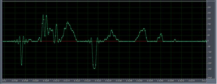
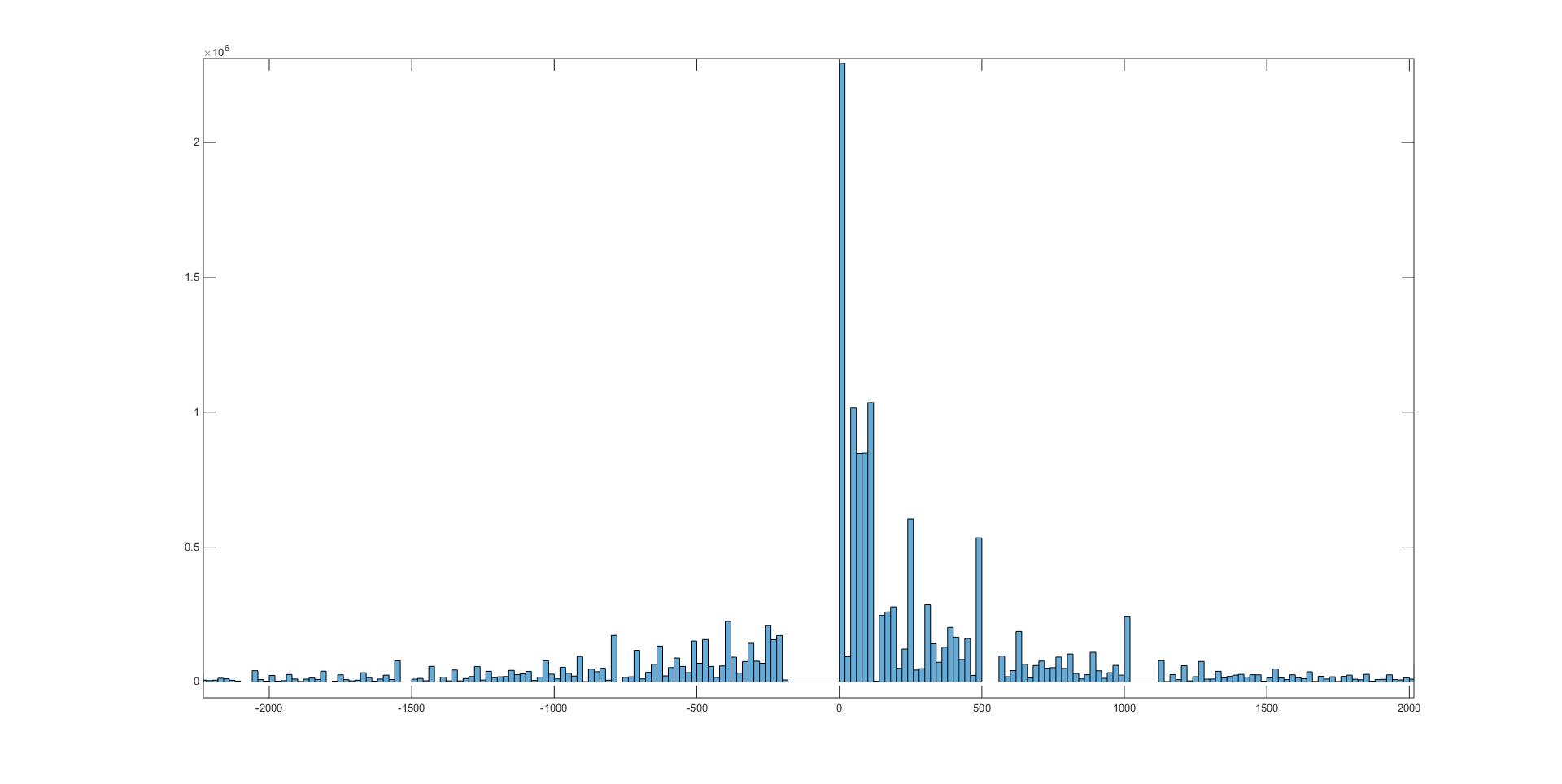
Following picture shows a silent part of my file. It is obvious that something is wrong, audio should be equaly distributed around zero point, but in my case majority of nonzero samples have positive values, only few are negative, and seams like there is some cutoff at zero point.

I guess it's something to do with those 4bits always being zero and sample representation, but can't figure out what am I doing wrong. Do you have any idea?

  • Are you "tying" ADC input to VREF/2 correctly? Please tell about ADC input circuit. Also picture is too small to see numbers on vertical axis to estimate noise amplitude. Could you provide shorter "recording", but with numbers on axis that we can see?
  • Hello Ilmars,

    Thanks for getting interested in solving this issue.

    The ADC input circuitry is microphone with preamplifier (adding gain and DC value = VREF/2 and audio bandpass filtering). The preamp IC out is directly connected to ADC input. When I watch this signal by the oscilloscope, it looks like a regular audio signal. DC offset is only 0.005%, I think it's acceptable, am I wrong?

    There is no wave file option for 12-bit resolution, so it is suggested to represent samples in 16-bit resolution,2's complement, left aligned, leaving the 4 unused bits (all zeros) at the end (bits 0-3), in LSB,MSB order of bytes.

    I did the ADC12 setup like this:

    ADC12CTL0 = ADC12ON + ADC12SHT0_2 + ADC12MSC;

    ADC12CTL1 = ADC12SHP + ADC12SHS_1 + ADC12CONSEQ_1 + ADC12SSEL_3;

    ADC12CTL2 |= ADC12DF;

    ADC12MCTL0 = ADC12INCH_0;

    ADC12MCTL1 = ADC12INCH_1 + ADC12EOS;

    ADC12CTL1 &= ~0xF000;

    And this is routine for sample reading:

    Result0 = ADC12MEM0;

    Result1 = ADC12MEM1;

    buf[cnt] = (uint8_t)Result0;

    buf[cnt+1] = (uint8_t)(Result0>>8);

    buf[cnt+2] = (uint8_t)Result1;

    buf[cnt+3] = (uint8_t)(Result1>>8);

    Here is a 'zoomed' picture of the recording you asked (one channel, second looks the same). Please take into account the left alignment, which adds 16 times amplification. And also, this is silence in my office, not in anechoic chamber, so there is some ambient noise present.

    The problem I see are continued zero points and some sample values never present, you will see that on the histogram below.

  • > DC offset is only 0.005%, I think it's acceptable

    Sure. DC offset is "don't care" as long as you are fighting with uneven distribution of ADC/preamp input noise. When you are done with it - only then you shall think of either hardware or software offset compensation, if any necessary. 

    >And also, this is silence in my office, not in anechoic chamber, so there is some ambient noise present.

    No good. You shall disconnect mic and ground preamp input. You shall provide ADC data of just preamp and ADC noise, not random ambient noise of for god' s sake, EMI of your room. 

    Please note that msp430 is little-endian, following manipulations are not needed:

    buf[cnt] = (uint8_t)Result0;

    buf[cnt+1] = (uint8_t)(Result0>>8);

    buf[cnt+2] = (uint8_t)Result1;

    buf[cnt+3] = (uint8_t)(Result1>>8);

  • Ok, Ilmars,

    I did what you asked, here is a file recorded with no mic and preamp input grounded: /cfs-file/__key/communityserver-discussions-components-files/166/silence.wav

    In past 2 days I recorded continuously on 5 devices (almost 10h of recording on each). These recordings contain my speech, music from a radio, car driving, and also a silence in anechoic chamber. Then I did analysis. None of this files contains sample values close to zero in negative domain (FFF, FFE,..., FF8 – in file: F0FF, E0FF,..., 80FF), not a single sample. This is actually seen on the first wave form I sent. No audio signal is zeroed like that, no matter what kind of noise is present. That’s why I sent a file with input, but low signal level (silence in my room). It is obvious that something is wrong with negatives close to zero, like they are all zeroed. I don’t get it.

    The only thing I do is read conversion memory register result and switch byte order, which is directed by wave file spec.

    By the way, I didn’t understand what you meant by manipulations not needed. I get a sample in 2’s complement format, left aligned, last 4 bits being zero padded, for example: 1010000101110000b=A170hex. I need to store it in reverse byte order (70A1) for wave file. Can you, please, explain what you meant?

    Thanks for your help!

  • >By the way, I didn’t understand what you meant by manipulations not needed.
    Because msp430 is little endian system. Just write ADC data into array of signed integers and you will see that byte order is what wave file needs.

  • Thanks, Ilmars,

    I didn’t know that.

    But, please, help me resolve the adc zeroing problem. Interesting thing is that when I changed the code to implement what you suggested, zeroing of small negative samples became even worse then before. Can it be some data readout problem?

**Attention** This is a public forum