This thread has been locked.

If you have a related question, please click the "Ask a related question" button in the top right corner. The newly created question will be automatically linked to this question.

Using XDS100v2 as a debugger for MSP432

Other Parts Discussed in Thread: MSP432-DEBUGGERS, MSP-FET, TM4C129ENCPDT

Hello,

for a university-project I am currently routing a debug-board which connects the Cortex Debug Connector (10-pin) to an XDS100v2. I have studied the pinout of both connectors and I am a bit mixed up since the pinout from texas jtag-wiki  doesn't match the Cortex-M Debug Connectors pinout especially the routing of nRST seems to be wrong (comparing ARM-20pin on the cortex manual and the TI-wiki).

TI 14-Pin only has nTRST but there is no such reference for the Cortex-M connectors. So on what pin do i have to route nRST from the cortex connector to the TI-14pin? is it nTRST? Or shall i keep it on GND?

best regards

Benni

  • Hello Benni,

    You would connect nTRST (TI 14-Pin) to nRESET (ARM 10-Pin). Have you looked at the MSP432-DEBUGGERS tools page?

    Regards,
    Ryan
  • thanks for your reply, no i havent checked the debuggers tool page. But how is it that there is a difference in pinout betwen the ARM-20pin on the JTAG-page and the cortex-M Debug connector pdf?

    best regards
  • I do not see this difference you are referring to.

    Regards,
    Ryan
  • ah..sorry my fault i looked at the 20 pin Cortex Debug+ETM connector ;)

    so everything is fine, thanks again
  • Hi Guys,

    seems that I have a problem getting the debugger to work. when I want to verify the connection or try to debug. I get the following error:

    The controller has detected a cable break far-from itself.
    The user must connect the cable/pod to the target.


    It seems i have made some mistakle in creating my Breakout board. I now post the schematics, as I don't find the errors. The set up is as follows:

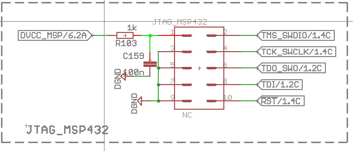
    I have a main board with the MSP432P401R attached to it and have a 10-pin 1.27mm header (like that one from the launchpad). I used the circuit connection from the launchpad schematic:

    since I cannot connect to the TI-14Pin from the XDS100v2 debugger I created a breakout board according to the pin out from your wiki:

    as i compare the pinout, i don't see the error. There is also no mix up in the signals from header to socket. So i don't get it, but obviously there's something wrong.
    I hope someone can help me with this.

    best regards

    Benni

  • Hi Benni,

    I have not seen this type of error before. Are you connecting the XDS100v2 to a custom board or TI EVM? Please refer to the MSP432 Hardware Tools User's Guide (SLAU571a), which shows the relationship between the ARM 10/20-pin connectors on the MSP-TS432PZ100 schematic as well as supplying the MSP-FET-432ADPTR schematic for converting the MSP-FET connector to ARM 10/20-pin.

    Regards,
    Ryan
  • Hey Ryan,
    thanks for your help, I will check the user guide. I am using a custom made board, but you see my connections in the schematics above. The breakout board connects the ARM-10 with the TI-14.

    best regards

    Benni
  • maybe there lies exactly the problem: The ARM-10 uses only Vcc sense from the Debugger, but in my custom board I connected that pin via 1k Ohm to DVcc, like in the launchpad schematics.
  •  Hey Ryan,

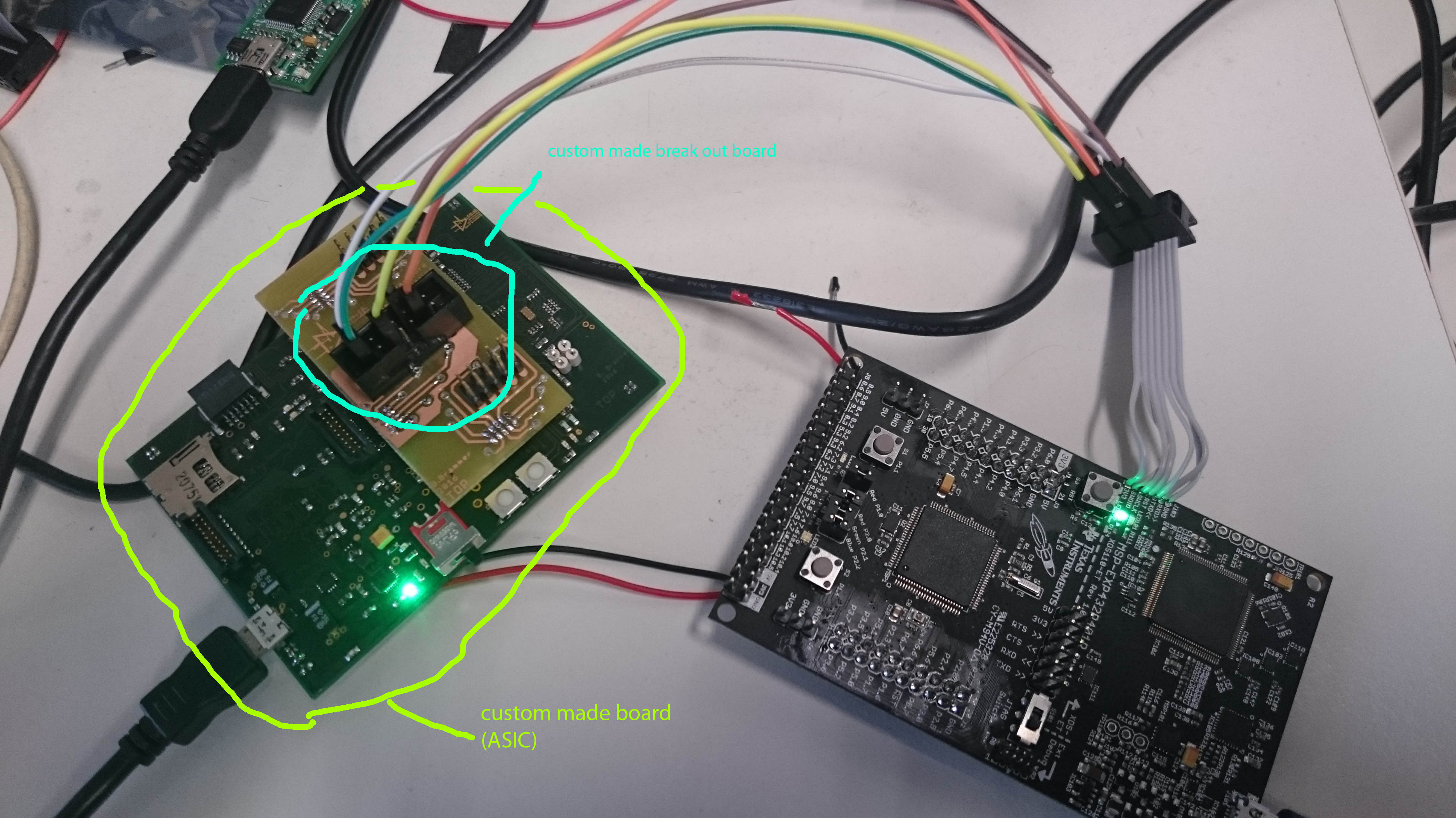
    after I checked really every possible error and found none, I used the evaluation board XDS110 debuger in SWO together with my custom board and the breakout board. Everything works fine, so there might be something wrong with the XDS100v2 debugger. I am using the latest CCS Version, this shouldn't be a porblem for the XDS100v2, or? here's a foto of my set up:

  • Benjamin,

    Are you aware, based on your picture and the test pins you're connected to on the MSP-EXP432P401R, that you are attempting to program the TM4C129ENCPDT used for the XDS110-ET as compared to using the EXT Debug pins on the opposite side of the board meant to program the MSP432P401R?

    Regards,
    Ryan
  • Sorry, what? I don't understand your answer.

    I am using the Launchpad's XDS110 debugger to debug my custom MSP432 board and it works absolutely fine just like it is descirebd in your MSP432P401R LaunchPad Development Kit (MSP-EXP432P401R) User's Guide (Rev. A).
    I have nothing to do with the TM4C129ENCPDT. I am using SWO. The opposite ARM-10 connector is to acces the MSP432P401R on the launchpad, but obviously i don't want that.

    But the big question is, why doesn't the XDS100v2 work? My layout is correct, otherwise I wouldn't be able to programm and debug my custom board. So whats the problem here?

    best regards

    Benni
  • Benni,

    I apologize for the confusion, as you mentioned previously something could be wrong with your XDS100v2 debugger. I do not have much experience with this particular tool and it is not developed the TI MSP team.

    Regards,
    Ryan
  • No problem, I have to apologize, since you're true. The XDS110 uses the TM4C129ENCPDT

    I will try to check with spectrum digital considering the XDS100v2. But so far debugging with the XDS110 works absolutely fine.

    Thanks!

    best regards

    Benni

  • Damn. for some reason, i don't know. I tried a debug session but got the following error message, and now nothing works anymore :(

    CORTEX_M4_0: Error occurred during flash operation: Target failed to read 0xE004300C

    CORTEX_M4_0: Error occurred during flash operation: Target failed to read 0x4000480C

    CORTEX_M4_0: JTAG Communication Error: (Error -615 @ 0x0) The target failed to see a correctly formatted SWD header. The  connection to the target may be unreliable. Try lowering the  TCLK setting before trying again. (Emulation package 6.0.228.0)

    CORTEX_M4_0: Failed to remove the debug state from the target before disconnecting.  There may still be breakpoint op-codes embedded in program memory.  It is recommended that you reset the emulator before you connect and reload your program before you continue debugging


    Actually i don't know what to do... reset everything disconnected, connected..but now nothing works anymore..Please could someone help?

    greets

    Benni

  • Ok. I checked if the Launchpad is stil working properly on its own, and yes it does. So I searched a little bit and finally found the important clue why the SDX100v2 doesn't work.

    In a similar post here in the forum ony guy managed to find the problem on his own: It's the TDIS pin. Sadly there is no marked hint on the TI wikis that if you use the xds100v2 probe on custom boards you'll have to set TDIS to GND otherwise the emulator will not work properly. I fixed that prblem and got a successfull verification of the Debug-probe.

    But sadly, this doesn't clear my last reported error :(
    I also tried a complete blank project from the ressource explorer but I still get the following error:

    CORTEX_M4_0: Error occurred during flash operation: Target failed to read 0xE004300C
    CORTEX_M4_0: Error occurred during flash operation: Target failed to read 0x4000480C
    CORTEX_M4_0: Power Failure on Target CPU: (Error -2063 @ 0x0) Unable to reset device. Power-cycle the board. If error persists, confirm configuration and/or try more reliable JTAG settings (e.g. lower TCLK). (Emulation package 6.0.228.0)
    CORTEX_M4_0: Failed to remove the debug state from the target before disconnecting. There may still be breakpoint op-codes embedded in program memory. It is recommended that you reset the emulator before you connect and reload your program before you continue debugging


    I also tried factory reset in the debug configurator, nothing. So what is the problem here? Please..

    best regards

    Benni

  • Ok. Now finally I managed to clear the error:

    First of all it seems that there were some greater changes according to the CMSIS porting because the project i launched was created and validated before March 2016 and worked absolutely fine. I used TI's conversion tool to convert the code, and the compiler didn't show errors BUT as i am using a hihger core voltage due to 48MHz operation I used the corresponding driver lib API. So after the porting my XMS432P401R crashed and I could only reset him with the factory reset procedure desrcibbed in the slau575d application note.

    So now I will try to programm a small project where i can validate the new APIs. Sadly I have to manually check my complete code, which I wrote befor March 2016 :(

    best regards

    Benni

**Attention** This is a public forum