This thread has been locked.

If you have a related question, please click the "Ask a related question" button in the top right corner. The newly created question will be automatically linked to this question.

MSP430 I2C Communication Using USCI Hardware and TI I2C Library

Other Parts Discussed in Thread: MSP430G2755
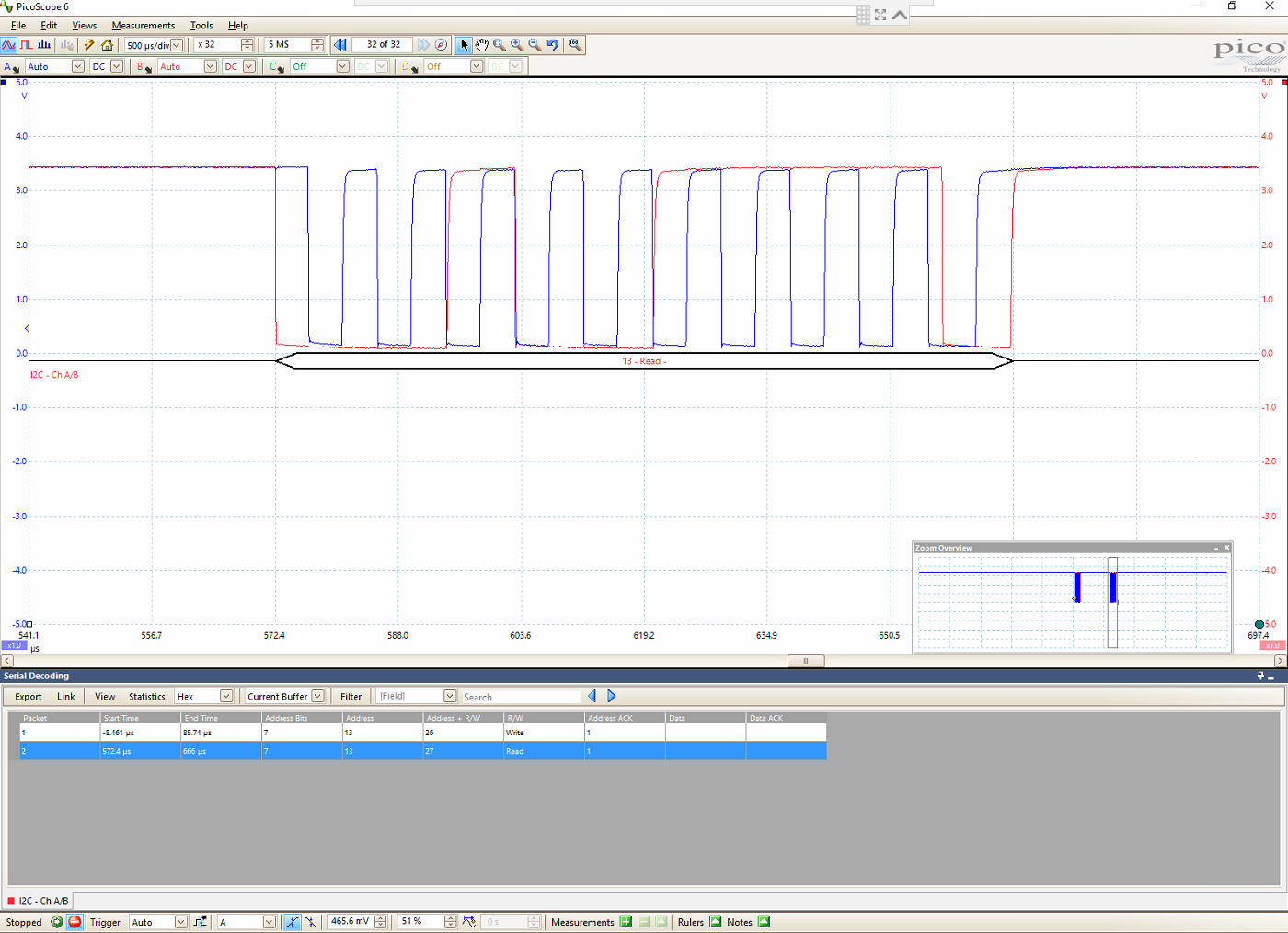
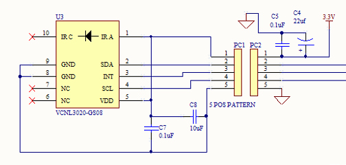
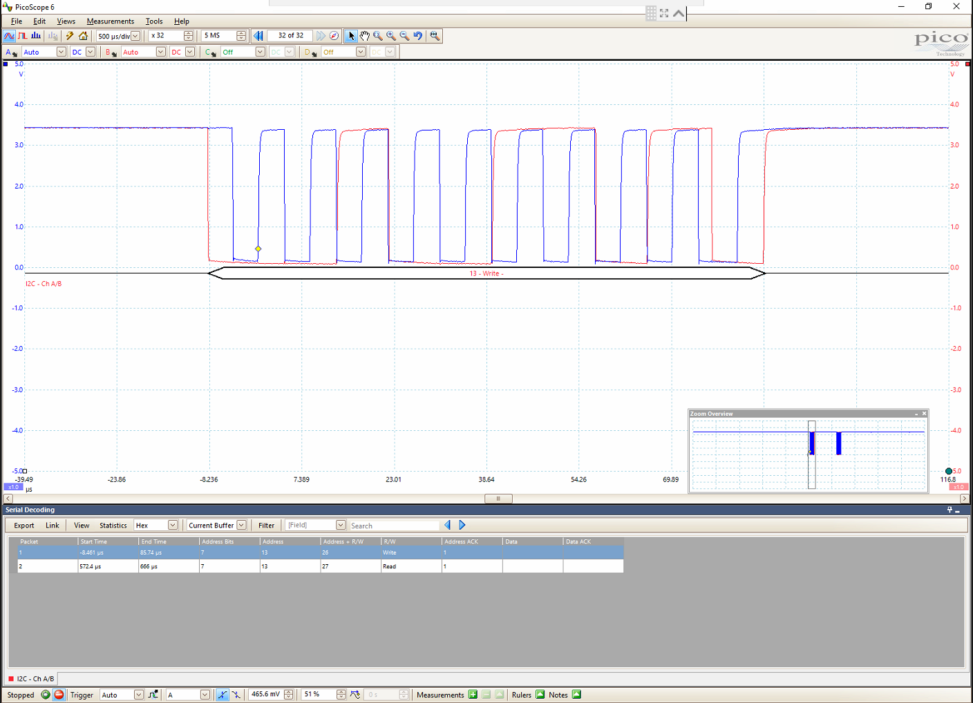
I've been trying to communicate with the VNCL3020 via I2C using an msp430g2755 and TI's I2C master library. I'm seeing a NACK from the VNCL3020 but the MSP430 isn't writing after so I think it's most likely that I have written some code incorrectly. My code has been tested with 4 VNCL3020 modules so the odds of them all being DOA are basically nonexistent, the SDA and SCL line are held high, I've tried multiple prescale values, and I've contacted Vishay to confirm that I have the module properly connected and that I am properly interacting with it. Attached are pictures of the oscilloscope readings associated with my code and a circuit diagram of how the VNCL3020 is connected.

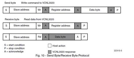
Communication Protocol:
I am trying to read from register 81h
Here is my code:

#include <msp430.h>
#include "TI_USCI_I2C_master.h"

#define IR_ADDRESS 0x13
#define IR_REGISTER_PRODUCT_ID 0x81
#define PRESCALE 0x44

unsigned char registerAddress = 0x81;
unsigned char productID = 0;


void main(void)
{
WDTCTL = WDTPW + WDTHOLD; // Stop WDT

BCSCTL1 = CALBC1_8MHZ;
DCOCTL = CALDCO_8MHZ;

_EINT();

//write register address
TI_USCI_I2C_transmitinit(IR_ADDRESS, PRESCALE); // init transmitting with
while ( TI_USCI_I2C_notready() ); // wait for bus to be free
TI_USCI_I2C_transmit(1, &registerAddress); // start transmitting

//read from register
TI_USCI_I2C_receiveinit(IR_ADDRESS, PRESCALE); // init receiving with USCI
while ( TI_USCI_I2C_notready() ); // wait for bus to be free
TI_USCI_I2C_receive(1,&productID);
while ( TI_USCI_I2C_notready() ); // wait for bus to be free

LPM3;

}


Any advice, suggestions, or resources would be greatly appreciated.
Thanks,

Christian

  • The oscilloscope traces have proper waveforms and the correct slave address, but there is no evidence that the VCNL3020 is actually there.

    There does not appear to be a problem with the software (except that you're not checking for errors).
    How exactly is the device connected to the MSP?
  • The SDA on the VNCL3020 is connected to SDA (P3.1) on the MSP430 and the SCL on the VNCL3020 is connected to SCL (P3.2) on the MSP430. When I asked Vishay support about this problem, one of the things they sent back to me is my oscilloscope reading with the bits identified.

    I'm assuming this is an accurate identification of each part of the write operation and that the NACK is proof of existence of the VNCL3020 but I am not certain enough to assert these assumptions as fact.

  • The SDA/SCL signals use an open-drain bus, so a high level just means that nobody pulled the line low. (This is why low-to-high transitions do not have a sharp corner; nobody actively drives the high signal.)

    In other words, a NACK shows that the other device is not answering. This might be done deliberately (last byte in a transaction, etc.), but the same happens if the other device is not working at all, or not there.

    You did not mention any pull-up resistors, but without them, you would not have gotten correct signal shapes.

    Are you sure that there actually is a connection between the VCNL and the MSP? What's this PC1/PC2 in the schematic?
  • Thank you for the explanation, PC1 and PC2 are connectors. I'll re-verify a proper connection and report back.
  • You were correct about the device not being present, it seems that the reflow soldering profile was damaging the chip. After changing the soldering profile, I got the expected response but after the first response the VNCL3020 held the line low and I couldn't communicate with it any longer, even after power cycling it.

**Attention** This is a public forum