


Hello every one!!!
I would like to know how to achieve the 1MSPS adc coversion with my MSP432, The first thing that I do is save all the ADC data in a vector(ADC_14_BUF), after that, I transfer the data from the MSP to my computer with UART to see the resolution of the ADC.
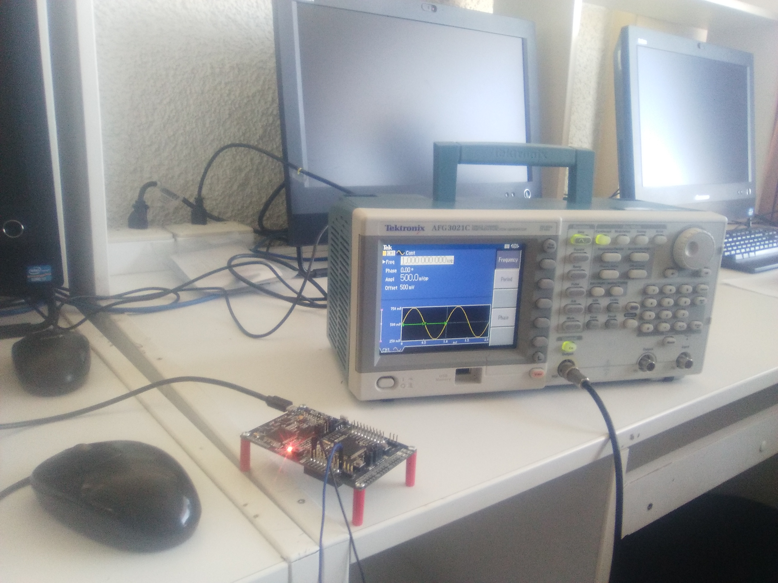
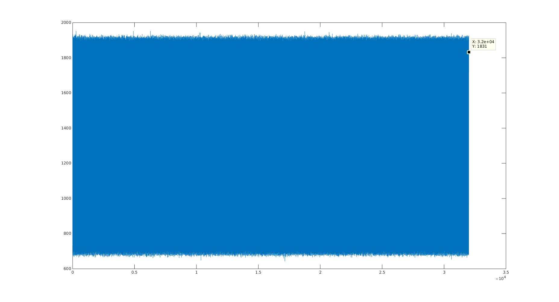
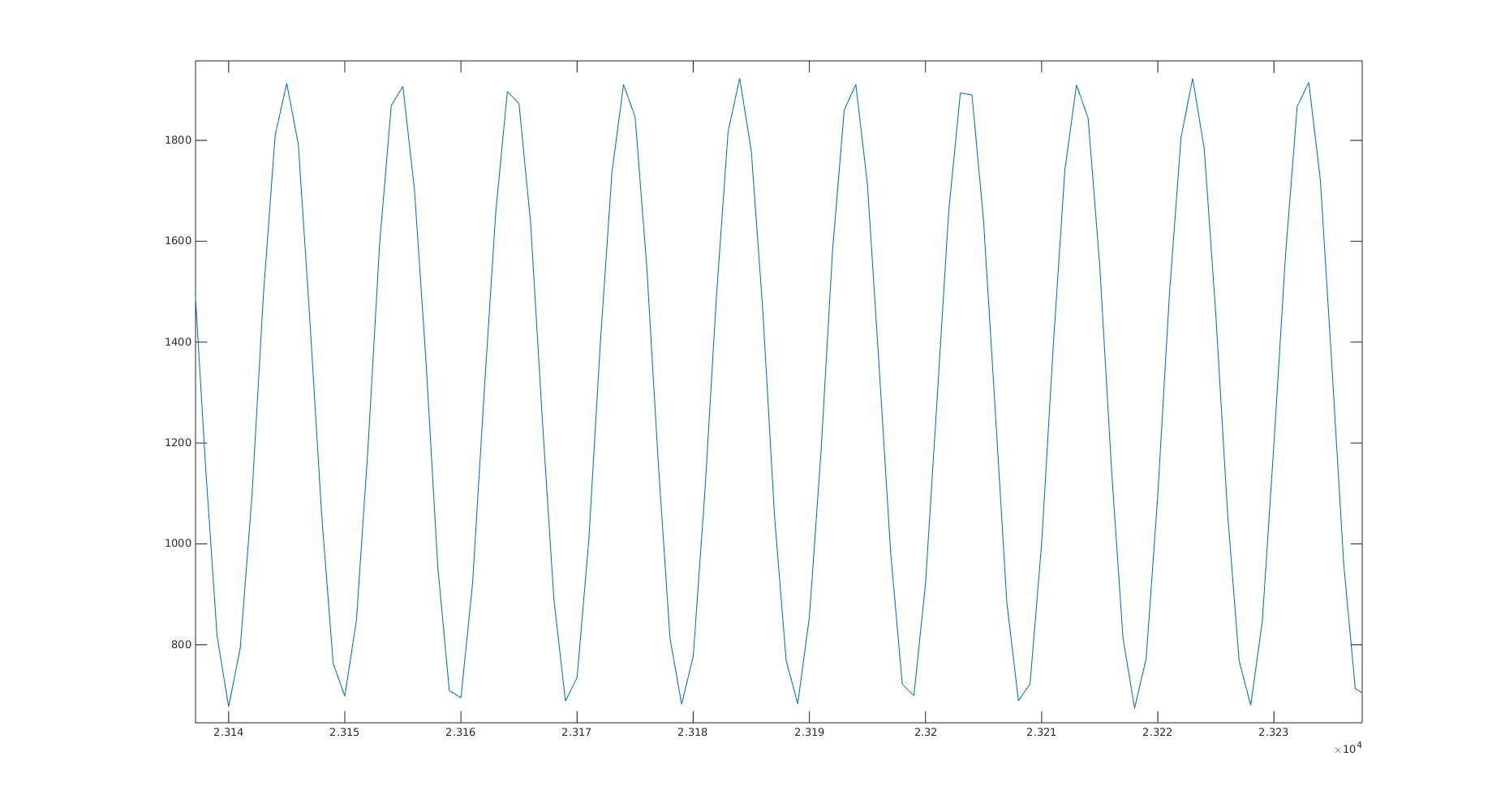
The signal is a sinewave with 4000 Hz(in the first photo 1000Hz but in the graphics 4000 Hz), as you can se it does not look like a signal that is sampled with a speed of 1MSPS :'v, Searching some information, I found that the only way to achieve the 1MSPS ADC is using DMA, but I only found DMA examples of the MSP using the DriverLib library. DMA would be another way instead of saving the information in my ADC_14_BUF vector.
-Is DMA the only way to achieve 1MSPs, if it is, Why???
-There are DMA examples for MSP432 that dont use the DriverLib librarie???
Code:
#include "msp.h"
#include <stdint.h>
#include <stdio.h>
#include <string.h>
#define length(x) (sizeof(x)/sizeof(x[0]))

volatile short ADC_14_BUF[32488];

//volatile short BUF_8[15000];
volatile long BUF_32;
volatile short i=0,j=1;
volatile long x=0,b=0,v=0;
static short s=length(ADC_14_BUF);

int main(void)
{  WDTCTL = WDTPW+WDTHOLD;                   // Stop watchdog timer

/*---------------------------------------------------------------------------------------------------------*/
    //Configuracion de la señal de CLK
  CS->KEY = 0x695A;                        // Unlock CS module for register access
  CS->CTL0 = 0;                            // Reset tuning parameters
  CS->CTL0 = CS_CTL0_DCORSEL_5;                   // Set DCO to 48MHz (nominal, center of 8-16MHz range)
                                           // Select ACLK = REFO, SMCLK = MCLK = DCO
  CS->CTL1 = CS_CTL1_SELA_2 | CS_CTL1_SELS_3 | CS_CTL1_SELM_3;
  CS->KEY = 0;                             // Lock CS module from unintended accesses
/*---------------------------------------------------------------------------------------------------------*/

  // Configure GPIO
  P5SEL1 |= BIT5;       // Enable A/D channel A0-A3
  P5SEL0 |= BIT5;

  __enable_interrupt();
  NVIC->ISER[0] = 1 << ((ADC14_IRQn) & 31);// Enable ADC interrupt in NVIC module

  ADC14->CTL0 = ADC14_CTL0_ON | ADC14_CTL0_MSC | ADC14_CTL0_SHT0__4 | ADC14_CTL0_SHP | ADC14_CTL0_CONSEQ_3; // Turn on ADC14, extend sampling time
  ADC14->CTL1 = ADC14_CTL1_RES_2;         // Use sampling timer, 12-bit conversion results

                                                                              // to avoid overflow of results

  ADC14->MCTL[0] = ADC14_MCTLN_INCH_0;                 // ref+=AVcc, channel = A0
  ADC14->IER0 = ADC14_IER0_IE0;                     // Enable ADC14IFG.3

  SCB->SCR &= ~SCB_SCR_SLEEPONEXIT_Msk;             // Wake up on exit from ISR

/*---------------------------------------------------------------------------------------------------------*/
    // Configuracion de los puertos UART
    P1SEL0 |= BIT2 | BIT3;                  // set 2-UART pin as second function

    __enable_interrupt();
    NVIC->ISER[0] = 1 << ((EUSCIA0_IRQn) & 31); // Enable eUSCIA0 interrupt in NVIC module

    // Configuracion de UART
    UCA0CTLW0 |= UCSWRST;
    UCA0CTLW0 |= UCSSEL__SMCLK;             // Pone eUSCI en reseteo
    UCA0BR0 = 26;                           // 48000000/16/9600
    UCA0MCTLW = 0x1000 | 0x0020 | UCOS16;

    UCA0BR1 = 0;
    UCA0CTLW0 &= ~UCSWRST;                  // Inicializa eUSCI
    UCA0IE |= UCRXIE;                       // habilita la interrupcion USCI_A0 RX
/*---------------------------------------------------------------------------------------------------------*/

    while(1)
    {
    ADC14->CTL0 |= ADC14_CTL0_ENC | ADC14_CTL0_SC;        // Start conversion-software trigger

    }

}


// ADC14 interrupt service routine
void ADC14_IRQHandler(void)
{
    if (ADC14->IFGR0 & ADC14_IFGR0_IFG3)

    	{
			ADC_14_BUF[i++] = ADC14->MEM[0];
    	}
//			for(i=0;i<= s+1;i++){ADC_14_BUF[i] = ADC14->MEM[0];}

		    if(i >= s)
		    {
		      if(j <= s)
		      {

		    	for(v=0;v<=4799;v++)								//ESPERA
		    	  {while(!(UCA0IFG&UCTXIFG));UCA0TXBUF = 'i';}

		    	for(j=0;j <= s-2;j=j+2)   //s+1
		    	{
					BUF_32= ADC_14_BUF[j+1];
					BUF_32= (BUF_32<<12)|ADC_14_BUF[j];
					//ADC_14_BUF[j+1]<<12;
					while(!(UCA0IFG&UCTXIFG));
//					BUF_8[x]=(BUF_32 & 0x000000FF);x=x+1;
					UCA0TXBUF = (BUF_32 & 0x000000FF);
					while(!(UCA0IFG&UCTXIFG));
//					BUF_8[x]=(BUF_32 & 0x0000FF00)>>8;x=x+1;
					UCA0TXBUF = (BUF_32 & 0x0000FF00)>>8;
					while(!(UCA0IFG&UCTXIFG));
//					BUF_8[x]=(BUF_32 & 0x00FF0000)>>16;x=x+1;
					UCA0TXBUF = (BUF_32 & 0x00FF0000)>>16;

		    	}

		    	j=s+10;
		      }
		      BUF_32=0x00000000;
		      i=s+10;
		    }// acanga abajo va el codigo de desplazamiento
}

/*---------------------------------------------------------------------------------------------------------*/
// Rutina de interrupcion de UART
void EUSCIA0_IRQHandler(void)
{
   if (UCA0IFG & UCRXIFG)
    {
//      while(!(UCA0IFG&UCTXIFG));
    }
}
/*---------------------------------------------------------------------------------------------------------*/


