This thread has been locked.

If you have a related question, please click the "Ask a related question" button in the top right corner. The newly created question will be automatically linked to this question.

16 bit SPI reception with MSP432

To whom it may concern,

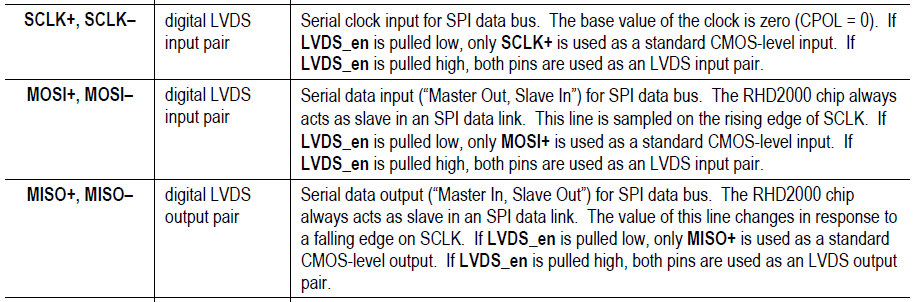
We are doing a project, in which we use a MSP432 microcontroller, with a chip that communicates via SPI.

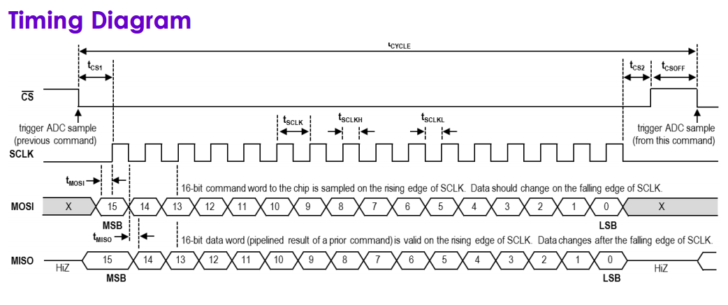
 This chip uses a 16-bit SPI communication and MSP432 is only able to send and receive 8 bits.

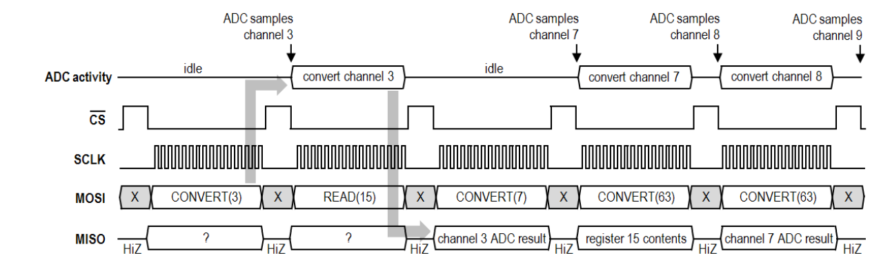
 We don’t have problem with the transmission by the MSP432, because you can make the MSP432 send 16 bits consecutive.

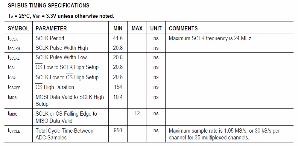
 But the MSP432 isn’t able to receive 16 bits. Because the chip doesn’t give much time to the MSP432 to remove the 8-bit word from the receiver buffer, when the chip is sending the new word (not new for the chip, because this send 16 bits, but new for the MSP432, who is waiting 8 bits).


Thus:

Someone has already implemented a solution to this problem with MSP432?

 Someone comes up with a solution to this?


Best Regards,

Santiago.

  • How fast is that SPI clock?

    Anyway, if your software is not fast enough, use DMA instead.
  • You are the first one who said that SPI is capable of sending 16 bits. SPI has 8-bit data bus only.

  • ... I read again. I understand, you have another chip that is capable of 16-bit SPI mode. But this nothing changes. SPI is a serial interface, so your cannot boost your speed on this interface. As I now understand the only thing you concern is how to make byte order correct in a hardware.

  • Configure bytes order on SPI of your 'another' chip accordingly.

  • What chip are you taking about?
  • Hi Santiago!

    Please provide some more information about the used counterpart. Normally the microprocessor is the master and since SPI is synchronous, the master gives the clock and therefore determines the speed of the transmission. Is the MSP432 the slave in your application?

    Dennis

  • The chip is RHD2132.


    The problem is not knowing the order, which is the top and which is the bottom.


    The problem is that the MSP432 is unable to receive consecutive 16 bits, when the MSP432 receives the first 8 bits, you need a "dead" time to remove from the buffer UCARXBUF, the first 8 bits, because this buffer have to be free when the next 8 bits are arriving.


    There is a flag in one of the records of the MSP432 called UCOE (Overrun error flag), which goes to 1 when you have data UCARXBUF overwriting new data arrives earlier because the buffer was not emptied on time. For us this flag is 1 because that is effectively what happens, do not have that dead time to empty the buffer before they start to get the other 8 bits that make up the 16-bit word that sends RHD2132.


    What we ended up getting, all the data out of phase. Because the whole mess that the MSP432 generate.

  • MSP432 is master and RHD2132 is the slave in the transmission. Look the answer below
  • I should rely on your statement that SPI buffer has only one byte buffer as implicitly described in official documentation. But I had no problem filling in 96 bytes to SPI buffer at full CPU speed 48MHz and 24 MHz SPI clock without any CPU wait-states.

  • If the MSP432 is the master, you won't have any problems with receiving multiple bytes. One byte after the other. The master provides the clock.

    Dennis
  • I assure you that. For testing, before having the RHD2132, we connect a MSP430 (as a slave) with a MSP432 (as a master) making the MSP430 send 16 bits (make send 16 is no problem). But the MSP432 couldn't receive, for the resson I explain earlier. The MSP430 (slave) didn't give the MSP432 (master) time to get the first part of the word. The MSP432 make a mix in the recive buffer, when the receive buffer is overwrote with the second part of the word.

  • Santiago Radi said:

    For testing, before having the RHD2132, we connect a MSP430 (as a slave) with a MSP432 (as a master) making the MSP430 send 16 bits (make send 16 is no problem). But the MSP432 couldn't receive, for the resson I explain earlier. The MSP430 (slave) didn't give the MSP432 (master) time to get the first part of the word.

    I'm not sure I understand this. The MSP432 is master, so is in control of the SPI clock. It only generates the clock when it has new data to transmit (ie TXBUF has been set). If the MSP432 has time to set TXBUF to trigger the transmission, why does it not have time to read RXBUF?

    Is there some reason the MSP432 can't wait until it has received the first byte from the slave before setting the next byte to transmit?

  • Hi Santiago!

    I agree to Rob C...I also don't understand your situation. Maybe you have a wrong idea about SPI? Look at the datasheet of your device - it says the following:

    "The RHD2000 chip always acts as slave in an SPI data link."

    This means it will never output any data if there is no clock provided by the master (your MSP). So clock in 8 bits and grab the first half of the data, then clock in another 8 bits and grab the second half. Once you have both bytes, combine them to a 16 bit word or do whatever you want with the two bytes.

    Dennis

  • Robert Cowsill said:
    Is there some reason the MSP432 can't wait until it has received the first byte from the slave before setting the next byte to transmit?

    At the rising edge of sending one bit from the first device, over device can at the same time send to the first one its own transmission bit. So the data transmission is actually synchronous full duplex.

  • Robert Cowsill said:
    Is there some reason the MSP432 can't wait until it has received the first byte from the slave before setting the next byte to transmit?

    I hadn't got any proofs that Santiago's issue is not a story-based. This includes his day-delay response, the chosen FPGA chip, which we cannot verify that it was programmed as 16-bit SPI and his other climes that SPI slave can send data without master clock and so on.

    If you think that he needs help from one of us, he should provide his 'sensitive' configuration, including source codes, hardware setup, etc. He could do it in private way, if he wants. Otherwise this thread is nothing more than a poker-game and fishing.

  • Alexey Bagaev said:
    Otherwise this thread is nothing more than a poker-game and fishing.

    ...with bluffing and disrespect to MSP platform, community experts, natural programming rules and so on...

  • I think tha you are not understanding the problem. To improve the situation I sent a picture of the data sheet RHD2132 which shows how it works the 16-bit SPI communication.

    I don´t need to send 8 bits, then a dead time and finaly the other 8 bits, I need to send 16-bit, all together. Because the MSP432 isn't abel to receive the 16 bits by default.

    Do you understand the problem?

    Santiago.

  • Franco,

    two eight bit transmissions act as a sixteen bit transmission. The slave doesn't care if there is a small pause in between. SPI is eight bits per default (USI can handle sixteen) and every transmission diagram in a datasheet looks like yours, but since the communication is controlled by the master, two consecutive eight bit transmissions is how it is done.

    Dennis
  • To confirm what Dennis wrote above, check the timing specification table in the datasheet:

    As you can see, there is no specified maximum for SCLK period, or high/low pulse width. There's no specified requirement for the clock period to stay consistent throughout a transfer either. This means it's fine to have a "long" clock cycle between the first and second byte.

  • Yes, there is. I admit that I forget to mention many things, even some I passed me like this:

    The RHD2132 has no internal clock. It uses the SPI CLK for to do its internal operations.

    As the figure shows, RHD2132 uses the 16-byte cycles to convert analog to digital the measured channels. Perhaps, if  the communication is cut in two parts

    as you say, the RHD2132 cannot continue sampling the signal.

    Parallely to you, I'm sending mail to the creator of this chip. So I would be interested to know if the MSP432 can receive 16 bits together.

     said to use DMA. Honestly I have no knowledge of how to use it, for to send 16 bits together.

  • Hi Santiago!

    Santiago Radi said:
    The RHD2132 has no internal clock. It uses the SPI CLK for to do its internal operations.

    I wanted to answer that I doubt that, but a look into the datasheet confirmed it - the device uses the SPI clock for internal operations. It needs a few dummy writes on the bus to do the calibration, for example. Never saw this before. Anyway - it doesn't make a difference here. The dummy writes are consecutive eight bit writes as well.

    Santiago Radi said:
    Perhaps, if  the communication is cut in two parts as you say, the RHD2132 cannot continue sampling the signal.

    It will not stop, it only has the very small pause in between the two bytes, but you will not notice that. It is the same for every sample. The datasheet even recommends to add three auxiliary commands to be able to insert commands different than the CONVERT one while maintaining a fixed period for each round-robin command sequence. This means you will insert further delays.

    Santiago Radi said:
    So I would be interested to know if the MSP432 can receive 16 bits together.

    It will never receive sixteen bits in one cycle because the receive buffer is only eight bits wide. The DMA mentioned by Clemens will improve the transmission speed because it can move the data from the receive buffer to another memory location without the interruption of the program, but you do not necessarily need it here.

    Dennis

  • Santiago, are you connecting such electronics directly to the brain or just to the peripheral system?

  • It will never receive sixteen bits in one cycle because the receive buffer is only eight bits wide.

    I had a hard time believing this - most Cortex-M MCUs I know allow up to 24 bit at one transfer. However, checking the reference manual, this is correct. Not sure what drove TI's decision here, beside compatibility to a semi-paleolithic 16-bit core ...

    So I would be interested to know if the MSP432 can receive 16 bits together.

    Yes, it can (send and receive) - as two separate, consecutive 8-bit transfers. As long as the MSP (master) does not pull the CS line up during transfer, that will not matter.

  • f.m, I see, you decided also to subscribe. By the time you will wait for something interesting you can see on the Internet how an astronaut on the International Space Station failed to dock a cargo ship.
  • Speaking about space missions, I'd rather like to see some footage of the failed pre-Gagarin Russian/Soviet attempts, that ended like the Challenger mission '86...

    By the time you will wait for something interesting ...

    Well, still taking every opportunity to learn, sometimes from watching others. Didn't know much of the MSP432 before. Now I learned (so it seems) the MSP432 is basically a rehash of MSP430 peripherals with a Cortex-M4 core. Not sure if I'm impressed. Reminds me of the Freescale Kinetis M4 parts, which have mainly 8-bit peripherals implemented ...

  • f. m. said:
    semi-paleolithic 16-bit core ...

    Currently I rely mostly on such 16-bit cores. And they cost even more than MSP432.

  • f. m. said:
    a semi-paleolithic 16-bit core ...

    Such cores are actually 20-bits. The data bus is a 16-bit wide.

  • Currently I rely mostly on such 16-bit cores. And they cost even more than MSP432.

    Perhaps because of "being semi-paleolithic". There exist even more pre-paleolithic 8-bit cores that aren't really "cheap". And if it was not for the fierce price competition of Cortex-M0 cores, they would be even more expensive (Hello MCP !). A nice name for this trap is "customer lock-in". I'm glad I escaped this 8-bit world (company), with all it's dark dungeons and labyrinths ...

  • f. m. said:
    A nice name for this trap is "customer lock-in".

    Probably you are right. I like the performance and capabilities of ARM Cortex M4F, but there are quite big list of factors what were not included in MSP432 platform, but there are in 20-bit MCUs.

  • Such cores are actually 20-bits. The data bus is a 16-bit.

    I know there is an "extended" variant, with 20-bit address range, and the respective instruction set support. The main core architecture remains 16-bit. And, the extension comes with a 10 .. 20% performance penalty - longer instructions require multiple fetch cycles. Instruction size is basically independent of architectural width, but determined by instruction count, address modes and operands. That is a clear advantage of 32-bit cores. Most ARM-Thumb2 instructions are 16-bit wide, thus one fetch gets two instructions.

    Not saying 8-bit or 16-bit MCUs are "bad". They are a product of their time, using the available resources (number of transistors/gates the technologies allowed).
     

  • f. m. said:
    Speaking about space missions, I'd rather like to see some footage of the failed pre-Gagarin Russian/Soviet attempts, that ended like the Challenger mission '86...

    Soviet/Russian space program was based on Nazi trophy technologies (rocket engine, gyro) also. Just didn't want to talk about it on TI's forum. But if you wish there are plenty video documentations on YouTube about what do you want to see.

  • PS: Except of pre-Gagarin. This probably will never be in public, if they took place.

**Attention** This is a public forum