This thread has been locked.
If you have a related question, please click the "Ask a related question" button in the top right corner. The newly created question will be automatically linked to this question.
After succesfull debug of my project with msp430g2553 (not launchpad) I faced with a problem on standalone run.
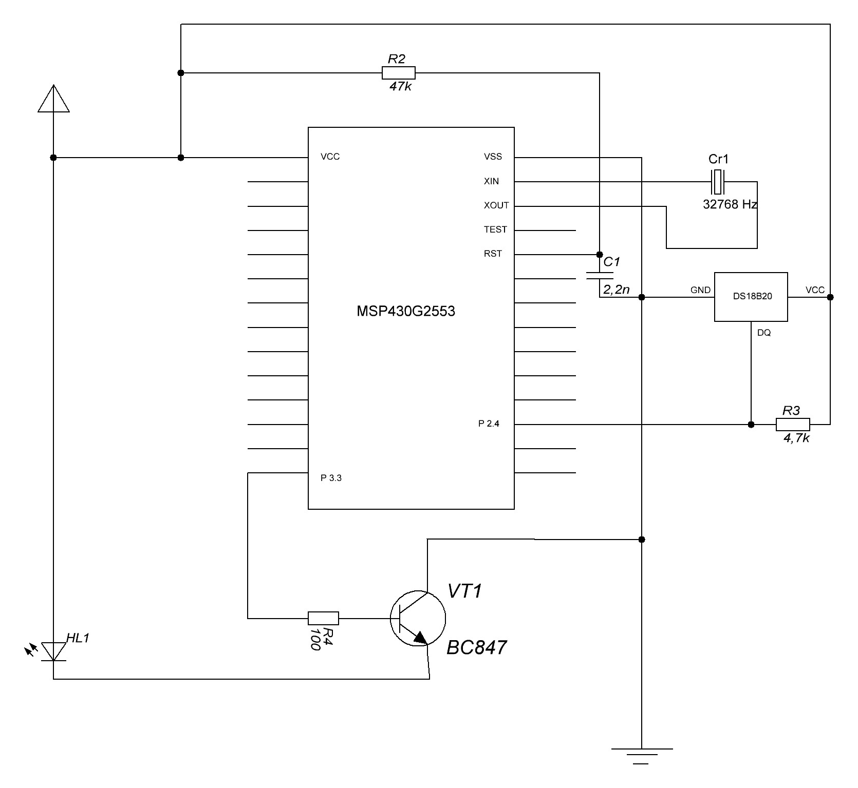
Due do datasheet, /RST pin pull-uped with 47k resistor to VCC. No success.
Than I pulled-down /RST to GND with 2,2nF capacitor without any effect.
After some googling I also soldered 0,1 uF capacitor between GND and VCC but still circuit don't work out of debug.
During the debug /RST has voltage level 3,1 V, in standalone run - 0. It is obvious that problem is there, but how to pull it up correctly?
UPD I also tried capacitors 100n, 4,7uF and resistors 1k, 10k, 0k (direct wire) and source circuit from battaries but with no luck. In debug mode program works perfectly in any of such RC's.
As a programmer I use Launchpad f5529.
So this is the schematics. It is very simple application: using DS18B20 temperature sensor MCU periodically measures temperature and if it higher than needed sends a kind of "TURN ON"command to my A/C via IR LED. As I mentioned above everything works perfect during the debug mode.
Thanks for your reply.
The schematics look fine. But you did not show the battery.
When all connected in the stand alone mode.
1. What is the measured voltage between the battery + and – terminals while in use?
2. What is the measured voltage from a to b?
3. What is the measured voltage from c to b?
4. What is the measured voltage from d to b?
Your first posting says: During the debug /RST (d) has voltage level 3,1 V, in standalone run - 0.
OCY, thanks for your reply. Here is fresh measurements:
ab - 3,57 v
cb - 0 v
bd - 3,39 v. And this looks very strange! During my first measurements it was always 0. May be I was mistaken yesterday somwhere, or it was because the bad soldering... very strange. I checked the circuit several times.
So now I can state that RST pin works as it should. But the problem remains the same and nothig happens out of debug.
Let me say some words about debug. I have an IR-analyzer made with AVR mcu which catch IR pulses and print timings over rs232. This circuit I use few years to decode RCs and make my own controllers for home automation. So out of debug it catches nothing, my problem is not sounds "I CAN'T TURN ON MY AC", just "my MCU circuit does'nt works %-)
Hi Sergii!
What type of battery are you using? Is it capable of providing enough current? Look at R4 - without the internal output resistance of P3.3, this path would already draw about 30mA. And HL1 doesn't have any current limiting resistor at all. Maybe while debugging you got additional power from the FET, but the battery has too high input resistance. So when the transistor turns on, the supply for your circuit drops, causing a reset, over and over again. You should add a resistance for HL1 and you should also increase the resistance of R4. If the current gain isn't enough, use a Darlington NPN or a FET. Do you have a bench supply? I would test if the circuit works with a higher current capable supply.
And add some decoupling capacitors to the MSP's supply pins - a 10µF + 0.1µF in parallel would be OK.
VT1 has a wrong orientation, but I think you already noticed that.
Dennis
Hi Dennis! Thanks for your comment.
I tried to run this circuit with Launchpad's supply pins, CR 2032 battery, Nokia battery BL-5CA (3,58v), 2 AAA elements without any luck.
To check your suggestion about current draw I totally removed transistor, 100 Ohm resistor from its' base, IR LED and even DS18B20 sensor and changed the program to send some number through UART periodically. The result is still the same - the device works only during the debug session. And yes, I added decoupling capacitors to the MSP's supply pins - a 10µF + 0.1µF in parallel. Ufff, this is kinda strange))
Yes, I understand that it is hard to see anything and requires some paintings. But if assume that everything was soldered up to schematics, do U have any idea what could cause the problem? I am going to develop a new PCB and solder it again 'coz see no solution with this one.
Sergii Matsiievsky said:Nope. I have another Launchpad with msp430f5529 and use just it's FET to load firmware into msp430g2553. This last controller is in 28 TSSOP package and soldered to circuit. In Launchpad jumpers between FET and main board disconnected (3,3v, GND, TST, RST). Every flashing is succesfull, I don't see any problem here. I also did it with MSP Flasher 1.3.9 and it was succesfull too.
I am confused now. You are now saying: "... I don't see any problem here ...", and "... and it was successful too."
Does "successful" here include the G2553 runs standing alone after that?
P.S. some debugger or MSP Flasher may be able to flash the code correctly, but may lock-up the G2553 in a non-cooperative way. afterwards. You need to completely power-down and then power-up the G2553 in order to run the code standing alone.
old_cow_yellow said:I am confused now. You are now saying: "... I don't see any problem here ...", and "... and it was successful too."Does "successful" here include the G2553 runs standing alone after that?
P.S. some debugger or MSP Flasher may be able to flash the code correctly, but may lock-up the G2553 in a non-cooperative way. afterwards. You need to completely power-down and then power-up the G2553 in order to run the code standing alone.
The connection at RST is the one I would also check first if the MSP does not start to run the application. Maybe the capacitor is connected to GND, but the resistor does not have a proper connection to DVcc, so RST is floating with an unconnected debugger...?
I have the same problem with an MSP430g2001 custom board. I can download a program using CCS via TI FET, single step, and all is well. When the spy by wire emulator is disconnected, the code does not run and based on the power consumption it looks like the processor is held in reset.
47K pullup with a 2.2nF per the TI ref des and app notes.
Any suggestions?
**Attention** This is a public forum