This thread has been locked.

If you have a related question, please click the "Ask a related question" button in the top right corner. The newly created question will be automatically linked to this question.

F67xx AUX0OK flag does not set

Hi MSP champs,

I have a question about F67xx AUX.

I tested AUX module, when AUX1OK flag does not set timing, AUX0OK flag will never set.

Is this right behavior?

My test code is here.aux_test.zip

AUX1LVLx :110, then = Approximately 3.00 V

AUX0LVLx: 110, then = Approximately 3.00 V

When AUX1OK flag is 1, AUX0OK flag can change 1 or 0.

But, when AUX1OK flag is 0(AUXVCC1 is under 3.0V. But it is over 2.4V), AUX0OK flag will never set (1->0 is OK, but 0->1 is NG)

And, how should it set this AUX0OK flag in this case?

Regards,

Shinji Ueda

  • Hi Shinji,

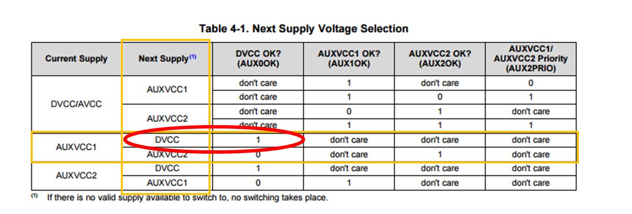
    Have you carefully inspected Table 4-1 of the User's Guide? Since AUX1OK is 0 (with AUX1LVLx set to 110b and AUXVCC1 under 3 V), the current supply is DVCC/AVCC instead of AUXVCC1 in which case the AUX0OK bit is in a "don't care" state. You would therefore not expect AUX0OK to be set at any time during this case.

    Regards,
    Ryan
  • Ryan-san,

    Thanks you very much.
    You said that this behavior is correct. right?

    > the AUX0OK bit is in a "don't care" state.
    This means, AUX module cannot set AUX0OK flag 1. correct?


    That means, This AUXxOK flag is not simple 'good/not good supply voltage' flag.
    Because when AUX0OK is 0 and AUX1OK is 0, then DVCC is over 3.0V. AUX0OK cannot set 1 by H/W.


    Regards,
    Shinji Ueda
  • Hello Shinji-san,

    The AUX module may not care or bother to set this flag to 1 while DVCC/AVCC is the current supply, this flag is meant to be checked while AUXVCCx is the active supply.

    Regards,
    Ryan
  • Ryan-san,

    I have an additional question about table4-1.

    Your first reply, you said that ' the current supply is DVCC/AVCC instead of AUXVCC1 in which case the AUX0OK bit is in a "don't care" state.'

    My test condition  is as follows,

    1. DVCC/AVCC is gone. then AUXVCC1 is current supply. (AUX0OK is 0)

    2. AUXVCC1's voltage under 3.0V. then AUX1OK is 0.

    3. Then, DVCC/AVCC comeback. It become over 3.0V.

    My understand is,

     I have to see the column, Current Supply is AUXVCC1, Next Supply is DVCC  correct?

     Then, I see [DVCC OK?]  column,  it is 1.  This means, if AUX0OK bit is 1, it can switch next supply.  

    Please see attached JPEG.

     But, you said 'AUX0OK bit is  in a "don't care" state'. I cannot understand your explain.

     Could you please teach me more details?

    Regards,

    Shinji Ueda

  • AUX0OK is only in a "don't care" state when DVCC/AVCC is the current supply. In the test case you mention AUXVCC1 is the supply so we now care about the status of DVCC. Nothing I have stated conflicts with Table 4-1.

    Regards,
    Ryan

**Attention** This is a public forum