This thread has been locked.
If you have a related question, please click the "Ask a related question" button in the top right corner. The newly created question will be automatically linked to this question.
Hi team,
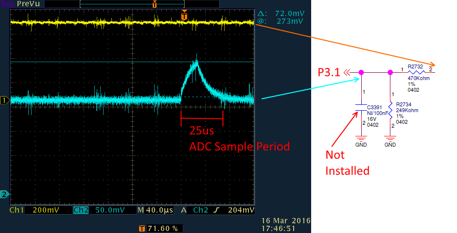
We're noticing a sawtooth wave when sampling with the ADC on P3.1. This sawtooth wave only occurs when the sample is taken. However this issue does not occur when we replace 470K with 100K and the 249K with 51K.
What are some reasons as to why this may be occurring with one set of resistor values but not with the other?
I've attached a picture of the waveform below.
Regards,
Akash Patel
This is how unbuffered SAR ADC of msp430 works. Try to measure input voltage which is equal to VREF and you will see different kind of sawtooth.
Sample capacitor have some residual charge after previous conversion. Voltage of ADC sample capacitor depends on voltage sampled at previous conversion, but usually it tends to reach VREF/2. This explains sawtooth when you sample voltages below VREF/2. This also explains why there's chapter in ADC documentation "sample time considerations". By reading particular chapter you also will understand why sawtooth decrease when you decrease impedance of ADC input circuit - in such case sampling capacitor reach input voltage faster,
Hello Akash!
First, thank you for providing a very detailed scope shot and circuit.
During sample time, an internal switch allows the input capacitance to be charged, which is reflected in the sawtooth wave. The required time to fully charge up the capacitor is dependent on the external analog front-end (AFE) connected to the ADC input pin. However, the sample time is directly impacted by the source resistance. As you observed, using higher-resistance resistors increases the required sample time. With the lower-resistance resistors, the input current is higher and thus charges up the input capacitor more quickly.
Take a look at Section 2.2 Selecting the Right Sample-and-Hold Time (SHT) in the Designing With MSP430FR58xx/FR59xx/68xx/69xx ADC app note. It shows an analog input equivalent circuit model (including source resistance and source voltage) and also an example calculation of the minimum sample time. For the internal capacitance and resistance, refer to Table 5-22 in the datasheet.
Hope this helps!
Regards,
James
MSP Customer Applications
**Attention** This is a public forum