Hello!
I'm having difficulties communicating with MCP23S17 I/O expander using SPI. I'm using IAR and Launchpad Rev.1.5 with MSP430G2553. Thing is, that attached leds don't even turn on. It even seems like master doesn't provide clock pulses or i'm missing something important. Maybe someone had experience with this I/O expander and with experienced eye could look what i'm missing. Unfortunately i don't have oscilloscope to look at outputs..
#include "msp430g2553.h"

// *** Global variables *** //
#define _CS	BIT5	//Set P1.3 as Chip Select

// *** Function prototypes *** //
void ConfigureSPI (void);	//Set up SPI communication

int main (void)
{
  // *** Set-up watchdogtimer and clock system *** //
  WDTCTL = WDTPW + WDTHOLD;		//Stop watchdog timer
  DCOCTL = 0;			//Select lovest DCOx and MODx settings
  BCSCTL1 = CALBC1_1MHZ;		//Set range
  DCOCTL = CALDCO_1MHZ;		//Set DCO step + modulation

  // *** Set up GPIO *** //
  P1OUT = 0x33;			//Turn pins LOW except P1.5(_CS) & P1.0
  P1DIR = 0xFD;			//Set Port 1 as OUTPUTS exc. P1.1

  ConfigureSPI();			//Configure MSP for SPI
  while (1)
  {
    //Set A port to OUTPUTS
    P1OUT &= ~_CS;			//Set _CS LOW
    UCA0TXBUF = 0x40;		//Send Control Byte
    while (!(IFG2 & UCA0TXIFG));    	//USCI_A0 TX buffer ready?
    UCA0TXBUF = 0x00;		//Access to IODIRA
    while (!(IFG2 & UCA0TXIFG));    	//USCI_A0 TX buffer ready?
    UCA0TXBUF = 0x00;		//Set to OUTPUTS
    while (!(IFG2 & UCA0RXIFG));    	//USCI_A0 TX buffer ready?
    P1OUT |= _CS;			//Set _CS HIGH
    __delay_cycles(10000);		//Simple delay
    //Send data to GPIOA address
    P1OUT &= ~_CS;			//Set _CS LOW
    UCA0TXBUF = 0x40;		//Send Control Byte
    while (!(IFG2 & UCA0TXIFG));    	//USCI_A0 TX buffer ready?
    UCA0TXBUF = 0x09;		//Access to GPIOA
    while (!(IFG2 & UCA0TXIFG));    	//USCI_A0 TX buffer ready?
    UCA0TXBUF = 0xFE;		//Turn ON OUTPUTS
    while (!(IFG2 & UCA0RXIFG));    	//USCI_A0 TX buffer ready?
    P1OUT |= _CS;			//Set _CS HIGH
    __delay_cycles(10000);		//Simple delay
   }
}
//Sub-programm for SPI setup
void ConfigureSPI(void)
{
  P1SEL |= BIT1 + BIT2 + BIT4;	//Set up pins
  P1SEL2 |= BIT1 + BIT2 + BIT4;	//Set up pins
  UCA0CTL1 = UCSWRST;
  UCA0CTL0 |= UCMSB + UCMST + UCSYNC;	//MSB first, Master mode, Synchronous mode (3-wire)
  UCA0CTL1 |= UCSSEL1;		//SMCLK
  UCA0CTL1 &= ~UCSWRST;		//Release USCI for operation
}
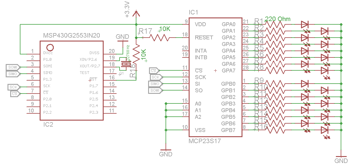
Simple schematic: