This thread has been locked.

If you have a related question, please click the "Ask a related question" button in the top right corner. The newly created question will be automatically linked to this question.

Unknown USB Device (Device Descriptor Request Failed)

Other Parts Discussed in Thread: MSP430F5529, MSP-EXP430F5529LP, MSP-TS430PN80USB, MSP430F5510, MSP-GANG

MSP Experts,

I am using an MSP430F5529 on a project as a simple UART pass-through to USB for a debug tool for our production product. I am unable to get my device to enumerate properly with the PC.

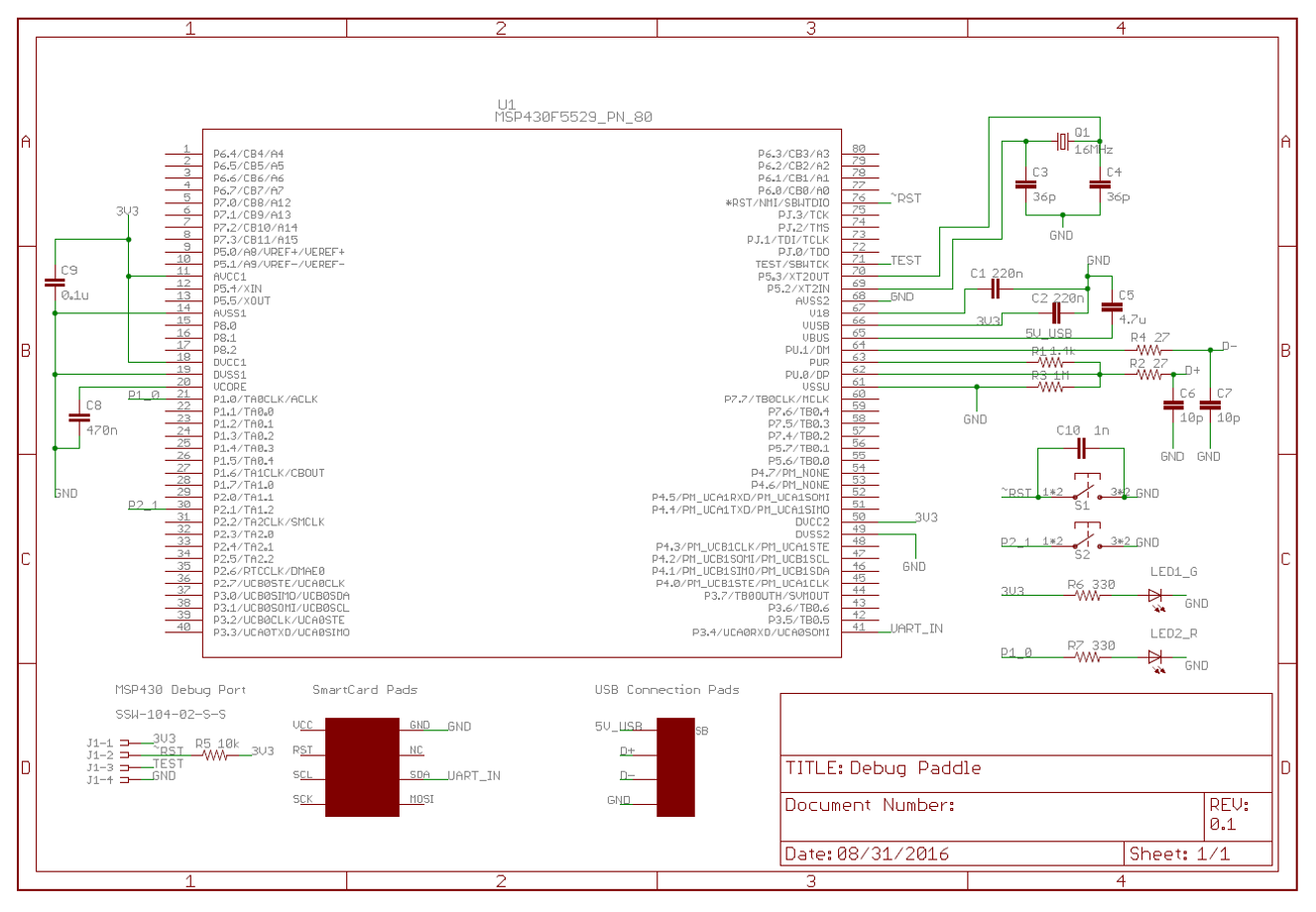
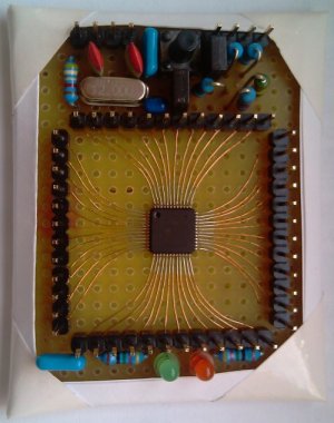
I have followed the hardware design of the MSP-EXP430F5529LP (as well as slaa457a) and developed firmware based off of the basic CDC code example from the USB developer's package. When I program the LaunchPad, I'm getting the CDC device to enumerate to the PC and am getting successful communications back to the PC. However, when I program my custom board (schematic pictured below), the device does not enumerate, and the subject line is what is displayed for the device within device manager.

I have checked and updated the descriptors.h file (as well as hal.c) for correct XTAL and clock settings overall, and updating this did not change the outcome.

Is there something simple I'm missing here? What could be the cause of the code being able to enumerate on one device but not another? Does the crystal I use for USB have to be 4MHz?

  • There are a number of things that could be wrong, but let's start with the fact that the code seems to work on the launchpad.... This might lead me to believe that your hardware (trace layout on the PWB in particular) is the problem.

    Things to check:
    1. Put a 16 MHz Xtal on the launchpad and see if your code with the 16 MHz descriptor works.
    2. Put a 4 MHz Xtal on the custom board and see if your code with the 4 MHz descriptor works.
    3. Check to see if your USB D+ and D- traces are routed differentially with 90-Ohm differential impedance. They should be matched length and not have a lot of vias in the routed path.
    4. It looks like you have the 10pF caps on the wrong side of the series resistors. The 5529LP has the caps between the resistors and the MSP430 pins. Refer to www.ti.com/.../slaa457
  • One other item to check is to make sure you calculated and selected the XTAL load capacitance correctly. 36pF looks high to me. You should make sure you are getting a good 16 MHz clock from the XT2 circuit. Use the debugger to set the UCS and port settings to get the 16 MHz onto SMCLK and out to a port pin.
  • Brian,

    Thanks for the responses. Unfortunately I don't have replacement crystals lying around to populate either with the other value to see if it works. Also, both crystals are very different footprints so it would be a hack-up job regardless.

    I swapped the caps on the USB data lines to the other side of the resistors (with a cut trace and jumper wire), no luck there (or at least no change in behavior). D+ and D- are within 0.2-Ohms of each other in impedance (each at about 27.6-Ohm from USB pad to MSP pin), so that's all good.

    The crystal I'm using (16MHz from Abracon - ABLS-16.000MHZ-B4-T) has a 18pF load capacitance. With the two 36pF caps in series (through GND), that should be hitting the 18pF load right on. I'll get a simple code example (not running any USB) to output the clocks and scope that and hopefully be able to see something there.
  • Just as an update to this thread, I ran a modified version of the MSP430F55xx_UCS_07 code example with my clock setup thrown in instead of the basic setup there. I scoped my clock lines and saw my MCLK (DCO) at 25MHz, as designed, and my SMCLK (XT2) at 16MHz, also as designed.

    I also played with the load caps on the crystal (even though it was running well, it looked like a low duty cycle), but still did not see an effect on USB enumeration. I dropped down to a 22pF load cap on each side, and re routed the clock out, only to see the same clock duty cycle, but a bit higher of a frequency since the load was dropped.
  • Another update -- I ran through the descriptor tool to make sure that the basic files were correct and that file wasn't messed up in any way. The generated output was functionally the same (I changed some strings in the descriptor tool - only actual differences) as what I was using. I'm honestly not seeing any differences in the SW so I'm thinking it is a HW issue, but not sure where to look.

    If anyone has a thought - let me know.

    BTW: two things TI needs to fix in a few different places --
    - In the usb.c function USB_determineFreq - the currentSELM does not check for DCOCLKDIV, just DCOCLK. This caused my code to think I was running at 12.5MHz instead of 25MHz. This had no functional bearing on my code.
    - In the MSP Descriptor Tool GUI there is an option on the MSP level to "Drive VBUS from External Supply" when the description talks about driving "VUSB from External Supply" (the latter of which makes sense). Just a typo that needs correcting.
  • Hi Tyler,

    Well, if you are following Figure 8 of SLAA457A document, then I see one difference in your hardware layout vs. what is suggested there. 

    - The 27 ohm resistors on D+ and D- lines should be placed after the 10pf capacitors and closer to the VBUS source.  In your hardware design, I see that these resistors are closer to the MSP430. 

    Other differences I see - no ESD suppressor or the diode on VBUS.

    Also thanks for pointing out some issues with the Descriptor Tool. 

    Regards,

    Arthi


  • Hi Arthi!

    Brian had noticed the capacitors being on the wrong side as well, so I went ahead and cut some traces and re-wired the board so that the capacitors were on the MSP-side of the 27-Ohm resistors. This didn't seem to make a difference.

    As for the ESD suppressor, it looks like that portion is faded (a bit lighter of a gray than the black of everything else) almost to seem to me like it is not required for USB connection. I also don't see one on any of the LaunchPad designs. Is this IC required?

    The diode on VBUS shouldn't be required either as we are fully bus powered, so no current should flow from our device back to the host. I also don't see this on the F5529LP design schematic.

    Two things I am going to investigate today:

    1. Using a 4MHz crystal (should show up from DigiKey sometime this morning) instead of the 16MHz crystal currently in use
    2. Decreasing DCO frequency running MCLK to decrease overall current draw of system

    To point (2), I read that the max current supplied by the MSP via VUSB was 12mA. According to the datasheet, the MSP itself will consume close to 11mA when running from flash with MCLK at 25MHz. That plus an LED and the other passives on the board have got to be pulling more than 12mA.

  • TylerWitt said:
    As for the ESD suppressor, ... I also don't see one on any of the LaunchPad designs. Is this IC required?

    The 5529LP has one. It's U404 and is right next to the USB connector. You have to remember that the LPs for the USB parts have a 2-port USB hub on them at the connector so that both the ezFET and the MSP430 can be connected to one USB cable.

  • Hi Tyler!

    Both MSP430F5529s have the suppressors (they are labeled TPD2E001DRLR). I am not sure whether it is the suppressor you need or the 0.1uF capacitor hanging off VBUS to GND. Also USB EVM board schematics for MSP-TS430PN80USB, MSP-TS430PN100USB and MSP-TS430PN64USB boards which are not hub devices have the supperssors and the diode and the 0.1uF capacitor.

    Regards,
    Arthi
  • All,

    As it turns out, the problem was not in the crystal frequency or the current consumption.

    The real culprit... following a few (apparently) incorrect drawings on the color coding of the USB wires. Top few Google image searches all agreed that white was D+ and green was D-, whereas I've found that it is the opposite.

    Thanks to all for helping on this thread. Issue is now closed/resolved.
  • The electrons don't know what color the wire insulation is. What matters is the pin to pin connectivity. But generally yes, D+ is white and D- is green, if the cable is wired according to the specification.

    Best results are obtained by consulting the official documentation (www.usb.org/.../ and not relying on The Google. The Google, like The Wikipedia, can be wrong.
  • Tyler,

    My MSP430F5510 p2p board on picture is far away from USB design rules, and it is working (USB projects) for last 5 years without any problems.

    For resolving problems (regarding USB) on your board, forget you application, and test it with preloaded TI BSL (4, 8, 12 or 24 MHz XT2). Simply, erase it (with SBW / JTAG), and after power up, device will enter to BSL mode and should be enumerated as HID. You can test it with TI BSL software tools.

    BTW, My SBW+ flasher (MSP-GANG like) has included 2 CDC - Mailbox / UART / I2C bridges for debugging or data exchange. With used both bridges in full duplex, UART can go up to 1Mbps.

  • Zrno Soli,

    Thanks for the tips, I'll keep that in mind for my next USB design!

    I was able to achieve the 1.15Mbps throughput I was looking for by buffering my transfers and sending them in the background, so all is good.

**Attention** This is a public forum