This thread has been locked.

If you have a related question, please click the "Ask a related question" button in the top right corner. The newly created question will be automatically linked to this question.

Interfacing MSP430f5529 to SD card reader

Other Parts Discussed in Thread: MSP430WARE, MSP430F5529

Hello,


I would like to ask regarding the Mass Storage Examples (MSC) under TI Resource Explorer>MSP430Ware>Libraries>USB Developers Package>Example Projects.

So I've gotten the Single-LUN File System Emulation Project to work. But the SD-Card Reader Project doesn't seem to work.

Details :

1) I do not have the MSP430F5529 USB Experimenter’s Board, hence I am working with a simple own made SD Card Reader. BUT I've checked with the schematics of the experimenter's Board and they are pretty similar (IMPORTANT Connections being the CLK, MISO, MOSI and CS)

2) I downloaded the MSP430 USB Developers Package which I've noticed is the same as the projects under TI Resource Explorer

3) By 'doesn't seem to work' I am referring to the program not sensing the Insertion/Removal of the SD Card, as I assume is what the program does - or did I misunderstand?

4) Do I have to copy the files created with the USB Descriptor Tool anywhere?


Is there anything specific that I might have to change in the program for it to work? Could you maybe provide me with some links regarding the SD Card interface?

Thank you very much in advance for your assistance.

  • Hi Zhek,

    1) I do not have the MSP430F5529 USB Experimenter’s Board, hence I am working with a simple own made 
    SD Card Reader. BUT I've checked with the schematics of the experimenter's Board and they are pretty
    similar (IMPORTANT Connections being the CLK, MISO, MOSI and CS)

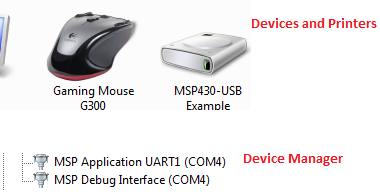
      How similiar are the connections?  What connections are not the same?  After you download the M2_SDCardReader example to your board do you see the MSC device in Device Manager?

    3) By 'doesn't seem to work' I am referring to the program not sensing the Insertion/Removal of the SD Card, as I assume is what the program does - or did I misunderstand?

    The example should detect the Insertion/Removal of the SD card as well as open/read and copy/paste files etc... 

    4) Do I have to copy the files created with the USB Descriptor Tool anywhere?

    If you are using the M2_SDCardReader example as is then it comes with its own set of descriptors.c/.h files.  If you are creating your own custom MSC SD Card example then you will have to save the newly created descriptor files to your project.

    usb.org has documents that describe the SD card interface.

    Regards,

    Arthi

  • Hi Zhek, 

    You shouldn't have to copy files from the USB Descriptor Tool anywhere. Can you provide schematics of how the MSP430F5529 is connected to the SD Card? Have you made any changes to the default project? Also, is it possible to probe the CLK, MISO, MOSI, and CS lines using a logic analyzer or oscilloscope to see if you are sending and receiving data correctly?

    Best regards,
    Caleb Overbay 

  • Hello Arthi,

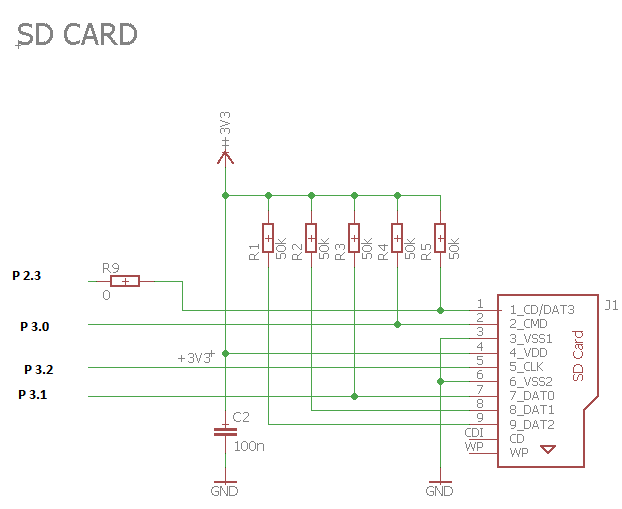
    This is the layout of my reader: Do you see a potential issue?

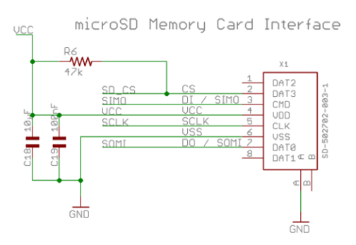
    I'll attach the one from the Experimenter's Board here as well.


    If by MSC Device you mean the Board then yes, but the SD Card (Neither Insertion/Removal) itself no. The potential issue is that I am using a SDHC Card (Size : 8 GB) which I have read could require some modification in the program - Might you have input on that? Anyway I ordered a 1 GB SD Card and it should be arriving today and I will try it out with that later.

    Ah thanks for that info regarding descriptor.c/.h files I'll be sure to pay attention to that in the near future. Also thanks for the link you provided, I'll check out usb.org.

  • Hello Caleb,

    Thanks for your input re- USB Descriptor Tool. The schematics is in my above response - both mine as well as the Experimenter's Board's.

    I didn't make any changes yet as I didn't need to since the FATFS library and required files are already included. The only thing that is missing so far is the integer.h file. Could that be a potential issue?

    I will follow your advice and probe it with an oscilloscope and get back to you.
  • Hi Zhek,

    Some items that might need to be re-visted in your schematic:
    1) TI's schematic shows 10uF capacitor hanging off of VCC to GND that is missing from your layout.
    2) TI's schematic does not show the various 50 ohm resistors connected to CD/DAT3(SD_CS), CMD(SIMO), DAT0(SOMI), DAT1 and DAT2.
    3) The port and pin connections designated for SD_CS, SIMO and SOMI are defined in the HAL_SDCard.c. Have these been changed to reflect your pin connections?
    4) TI's schematic does not show a 0 ohm resistor off of DAT3. DAT3 is used to sense the presense of the SD card, although USB stack does the detection via the software by writing CMDs to the MSC device and evaluating the response. You can look at deSelect() function to evalute how the detection of the card is done.

    Regards,
    Arthi
  • Good Morning Arthi,

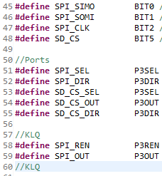
    I changed the port and pin connections under HAL_SDCard.c like this:

    Are they rightly written? However I am not sure about the PORTS (SPI_SEL, SPI_DIR, SPI_CS_SEL etc.) where exactly do i look for this info?

    I will make the layout changes you suggested and see what happens. Also in my physical layout there was no 0 ohm resistor on DAT3 because....yeah it was 0 ohm.

    But regarding the layout, do you feel mirroring the exact layout from TI's schematics will make the project work / a difference? My background in electronics is fundamental but I assumed the extra few resistors are for extra security and shouldn't really affect the way the program runs. Would love to hear your input on that as I am pretty new to the MSP430 family.

    Also yup, I am going through the mmc.c as well as the msc.c files slowly to see what does what and where. Thank you!

  • Hi Zhek,

    Since your schematic states the Port 2, Pin 3 (2.3) is connected to the CD/DAT3 line the following changes need to be made to HAL_SDCard.c file:

    SD_CS = BIT3

    SD_CS_SEL = P2SEL
    SD_CS_OUT = P2OUT
    SD_CS_DIR = P2DIR

    I am not sure whether layout changes to mirror what TI has will help because the rest of your board layout will matter too.  However, the layout changes cannot hurt since we know that TI's layout works.  I would suggest that you try out the software changes I listed above first and see if that helps.

    Regards,

    Arthi


  • Hello Arthi,

    Thank you for your reply. Sorry for the delay because I wanted to try a couple of things before i got back to you.

    I did what you suggested but it still hasn't sensed the insertion/removal of the SD Card. I've sinced changed to a normal SD Card ( 2 GB ) as well since I was using a SDHC card before this.

    1) I've also made changes to the mmc.c file, specifically in the frequency part #define DLY_US(n) __delaycycles (n* (25 / 1000000 )) of the program.

    2) I am afraid i am not too well-versed in the Pins/Ports topic although I have implemented your suggestions in your previous reply.

    PINS - Is it such that it depends on the second number of the Pin, eg. SPI_SIMO is on pin 3.0 hence BIT0? A follow-up question would be where can i go to learn more about the link between program and hardware pins?

    PORTS - from the Port Settings you provided above, I found the correlating Information in the datasheet :

    I don't quite follow this part. Why is it P2SEL? I would be very grateful if you could provide a short but linking explanation of how the ports relate with each other and the pins. Or perhaps point me to a documentation from TI that would make this clearer for me.

    I thank you in advance and have a nice day!

  • The MSP has a couple of ports, each having eight bits in most cases, some have less if the device is small.

    So there could be...

    Port 1

    • BIT0
    • BIT1
    • BIT2
    • BIT3
    • BIT4
    • BIT5
    • BIT6
    • BIT7

    Port 2

    • BIT0
    • BIT1
    • BIT2
    • BIT3
    • BIT4
    • BIT5
    • BIT6
    • BIT7

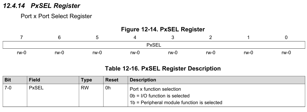
    Each port has different registers like a DIR (direction), OUT (output), IN (input), SEL (select), ...

    For port 1 all these registers would be P1DIR, P1OUT, P1IN, P1SEL, ...

    For port 2 all these registers would be P2DIR, P2OUT, P2IN, P2SEL, ...

    The eight bits of each port can now be addressed individually - "BIT0" is a definition for 0x01, "BIT1" for 0x02, "BIT2" for 0x04, ...

    So if you want to set BIT2 of port 2 to output direction, you have to set

    P2DIR |= BIT2; or P2DIR |= 0x04;

  • Hey Dennis,

    thanks for that! Really helped.

    I am now looking into the Digital I/O Module as well as the Port Mapping Controller in the datasheet.

    Btw i accidentally clicked verify answer oops.
  • Zhek,

    Please check out section 12 of this document: User's Guide

    That is the User's Guide for the F5xxx devices. It will explain all the peripherals in detail. Section 12 pertains to the GPIO modules.

  • Hi Zhek,

    I also recommend removing the 50K pull-up resistors from the data lines and leaving the 50K pull-up on the CS line. Also it might help to post the snippet of the code you've changed so we can take a look and verify it.

    Best regards,
    Caleb Overbay
  • I am following your problem closely, Zhek, and I was curious about whether the resistors are necessary. I read that the MSP430 has internal pullup resistor functionality, and I thought it is possible that the P3REN bit (that the sample code defined as SPI_REN) was the bit that enables/disables this functionality. Can anyone confirm this?

    This seems to be supported by the Users Guide documentation. And, in that case, do the ports know whether to function as pull-up or pull-down resistors by default? Or is that specified elsewhere?

    Thanks for any enlightenment anyone can offer.
    Travis
  • Ahh, I answered my own question. In the MSP430f5xxx family User's Guide, section 7, it says:

    7.2.2 Output Registers PxOUT

    ...

    If the pin is configured as I/O function, input direction and the pullup/pulldown resistor are enabled; the
    corresponding bit in the PxOUT register selects pullup or pulldown.
    · Bit = 0: Pin is pulled down
    · Bit = 1: Pin is pulled up

    So for the input pins, (MISO is the only MSP430 input that I can think of for this configuration) if you have enabled pull-up/down for, say, P2.6, then setting

    P2OUT |= BIT6

    would configure that pin to be pulled up, and 

    P2OUT &= ~BIT6

    would configure it to be pulled down.

    Not that anyone was asking this, haha, but I thought it would be relevant to the implementation you're working on.

    Cheers,

    Travis

  • Hi Travis,

    Thanks for your input on this! I'm glad you were able to answer your own question and its certainly relevant to the issue at hand.

    Zhek, have you made any progress on this issue you'd like to share?

    Best regards,
    Caleb Overbay
  • Hello Travis,

    sorry for the delayed response.

    I've been taking it slow while going through the document/chapters to make sure I understand the program as I go along. Mainly the GPIO modules as well as the UCSI SPI Chapter. So it might take a little while longer...

    I am glad you found a solution for your project(your follow-up bellow). Thank you also for your information regarding the configuration for the internal resistors, I am sure that will come in handy some day.

    I am curious though, did you manage to get it(SD Card Detection as well as File R/W project) to work in the end then? If you did, could you perhaps share the process in a simple manner? That would definitely be enlightening. Thank you.
  • Hello Caleb,

    Thank you for asking.

    Sorry for the delayed response. Have been at work on and off due to certain tasks.

    I haven't made any substantial progress in particular, as I've decided that I shouldn't jump ahead of myself and actually take the time to really understand what the program is doing.

    However if i were to discover something that would get the project to work in my case, be sure that i will share it here or perhaps start a new post as i am sure, that when i get to that point, there will certainly be follow-up inquiries.

    Thanks again and have a nice day!
  • Zhek,
    No, I haven't been successful in implementing the project yet. I'm fairly certain now that my hardware setup is correct, but I have not been able to detect the device as storage media after programming it with the M2 example. Part of this was due to FET programming issues I was having, which caused CCS not to recognize the device at all. I have since solved this by porting over my entire project to Linux and installing CCS there. I'm not certain why that solved the problem, but I believe it was a driver dependency issue that I was lacking.

    Anyway, I am still working on the project. Are you on a Linux host, by chance? If so, do you know where you would expect the storage device to appear when the SD card is interfaced? 'dmesg' command states that a USB Mass Storage device was detected, but it is not appearing as an external drive to my computer, so I'm not sure where I need to be looking for it.
  • Hello Travis,

    The project works!

    It was after a discovery of a mistake on my end. I made the assumption that the SPI MOSI/MISO/CLK/CS pins will be used (P 3.0 & P 3.1 & P 3.2 & P 2.3). And this is where I erred.

    After redoing the whole hardware configuration to make everything clearer and cleaner, and double checking the pin connections, I realized that in the schematics of the Experimenter's Board for MSP430F5529 , the connecting pins from the processor to the SD Card Reader Interface were P 4.1 & P 4.2 & P 4.3 and for Chip_Select Pin I used P 3.7 since all that was required was a high input.

    After making the above changes to the physical connections, I was able to detect the Insertion/Removal of the SD Card.

    As to your question, no unfortunately I am not on a Linux host. But the SD Card detection window popped up like what happens when you insert any normal usb into the computer.

    I guess the next part would be to integrate the SD Instructions from the FatFS Site by ELM-CHAN to write a more extensive program.

    Thank you for all your valuable input!

**Attention** This is a public forum